Download
1 / 23
230 likes | 319 Views
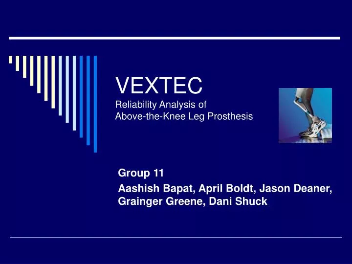
VEXTEC Reliability Analysis of Above-the-Knee Leg Prosthesis. Group 11 Aashish Bapat, April Boldt, Jason Deaner, Grainger Greene, Dani Shuck. Clarification of Technology.

E N D
VEXTECReliability Analysis of Above-the-Knee Leg Prosthesis Group 11 Aashish Bapat, April Boldt, Jason Deaner, Grainger Greene, Dani Shuck
Clarification of Technology We are developing a methodology to replace physical testing by performing testing and combining it with reliability analysis. This will reduce physical testing to reduce cost, time and increase quality. We can do this in either Excel or Matlab.
Reliability Analysis Tool Kit • Desktop Computational Reliability Model (DCRM) • Predicts fatigue failure • Simulates real material degradation models • How it works? • Grain structure of materials given conditions • Monte Carlo Probabilistic methods • Modeling of this early crack behavior • 3D Component Analysis
Is failure prediction possible? • VPS-MICRO™ was recently used to successfully predict the fatigue life for a production lot of 1000 turbine engine rotors. • Each rotor was simulated to include approximately 650,000 surface grains. • The simulation was conducted with 1.8 GHz Pentium desktop computer within 2 hours.
Market Analysis • Potential Medical device manufactures • Testing cost and time reduction analysis • Meetings with the medical device industry to identify specific market needs • Aid for FDA approval • FDA • Potential tool for the FDA to run preliminary design reliability analysis • Get approval as viable testing alternative for FDA requirements
Market technology to FDA and device manufacturer • Computer model replaces physical testing • One person doing a couple things versus 1000 people doing 1000 things • How big barrier is it to get FDA approval? • How much money and time? • How does FDA approve? • Will FDA accept simulation testing? How much money would it save? • How much money would it save to pick right design from start? How much time/ money is wasted with bad design?
Traditional Prosthetic Design • Trans-femoral prostheses: • Two interlaying sockets • Inner socket • Flexible (thermoplastic) • Cushions interface of residual limb • Outer socket • Less flexible, provides stability (hard thermoplastic) • Interconnection to upright assembly
Design Process • Computer-Aided Design (CAD) techniques: • Digitizer produces 3D image • Socket thermoformed to model • Positive casting of limb • Pylons made of titanium or aluminum • Range: flexible to rigid • Variable gait and comfort • Components fused via bolts, adhesives, laminating…
Current Design Disadvantages • Anchoring system failures • Stability • Adjustment: migration of limb in socket • Tightness/pressure: distribution of pressure load • Pending patents: ex. suspension straps
Past-Present-Future Methods • Conventional: • “Master molds” of plaster/corn-starch materials are heavy and fragile • Foam insulation/padding systems cause excessive heat • Current: • More readily machinable materials, enhanced stability • Future: • Myoelectric prostheses
Choose metal component • Find component with highest rate of mechanical failure • What are the loads on this component? • Once the component is found then transfer functions can be done to model the failure in other components • Then the test data will go through statistical analysis
Maude Database: 2000-2006 • 23 component failures in the knee • 14 Otto Bock • 4 Ossur • 5 Unknown Manufacturer • 5 component failures in the ankle/foot • 4 Ossur HF
Maude Database: 1970-2006 • 30 component failures in the knee • Otto Bock • Ossur • Mauch Laboratories • Chas A. Blatchford
Otto Bock Health Care • C-Leg Microprocessor Hydraulic Knee Joint • Tube Adapter for C-Leg • Free Walk Stance Control Knee/Ankle System • Socket Adapter http://www.ottobockus.com/PRODUCTS/LOWER_LIMB_PROSTHETICS/c-legoverview.asp
Mauch Laboratories, Inc • Mauch SNS Hydraulic Knee Control http://www.ossur.com/template110.asp?pageid=163
Chas. A Blatchford, LTD • 4 bar knee bolt • Short knee alignment kit http://www.blatchford.co.uk/prosthetics/products_ak/4-bar/4-bar.html
Ossur • Total Knee Model 2000 • Formitting Silicone Interface • I-540625 http://www.ossur.com/template110.asp?pageid=160
Types of Loads (by month or year) • Sedentary • Active • Are their gold standards out there? • Identify the load set. It will probably be a spectrum with a set number of cycles.
Loading on Failed Component • Loading is determined for failed component in prosthetic device • A loading scenario with tension, compression, and torsion components can be used for finite element analysis • Cyclic loading scenario is used for reliability/fatigue analysis
Resources • http://www.monash.edu.au/rehabtech/index.htm