Download
1 / 37
1.22k likes | 2.52k Views
NDT FOR COMPOSITE MATERIALS. Università Politecnica delle Marche Italy. SUMMARY. 1. Normative. 2. Main techniques used on FRP Components. 3. Specification for NDT Methods in FRP component. 4. Potential Trans-IND techniques for inspection of composite component for civil applications.

E N D
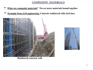
NDT FOR COMPOSITE MATERIALS Università Politecnica delle Marche Italy
SUMMARY 1. Normative 2. Main techniques used on FRP Components 3.Specification for NDT Methods in FRP component 4. Potential Trans-IND techniques for inspection of composite component for civil applications 5. Beam inspection by Ultrasound system 6. Deck inspection by Thermography system
Normative Very different techniques Non destructive testing Very different application Always in evolution It is important to have a normative to apply these techniques correctly ASTM Standard
ASTM E 543-04 • ASTM 543-04 norm report the list of all NDT norms • There are the lines guide to evaluate testing and safety agencies • There are a short description of the equipment for each nondestructive testing. • There is an important table with the comparison of NDT methods
E07 on Nondestructive Testing REVISION OF STANDARD Volume 03.03E 569-07 Practice for Acoustic Emission Monitoring of Structures During Controlled StimulationE 1106-07 (Includes change to title) Test Method for Primary Calibration of Acoustic Emission SensorsE 1211-07 Practice for Leak Detection and Location Using Surface-Mounted Acoustic Emission SensorsE 1816-07 (Includes change to title) Practice for Ultrasonic Testing Using Electromagnetic Acoustic Transducer (EMAT) TechniquesE 1888/E 1888M-07 (Includes change to title) Practice for Acoustic Emission Examination of Pressurized Containers Made of Fiberglass Reinforced Plastic with Balsa Wood CoresE 1932-07 Guide for Acoustic Emission Examination of Small PartsE 2192-07 Guide for Planar Flaw Height Sizing by Ultrasonics REAPPROVAL OF STANDARDVolume 03.03E 431-96(2007) E 650-97(2007) E 1495-02(2007) E 1774-96(2007) E 1814-96(2007
Signal conditioning Emitter SIGNAL MEASUREMENT Receiver Main techniques used on FRP Components • Ultrasonic Testing (contact and non contact) Ultrasonic testing is used to detect delaminations, porosities, cracks or inclusions. It is also possible to determine the thickness, fibre distribution, fibre alignment, and the curing state. The ultrasonic probe emits ultrasonic waves into the material. These waves are reflected by the face opposite to the probe. The probe collects these signals and they are visualised on a screen. So the thickness can be determined of the sonic velocity of the material is known. If there is a defect, an inclusion or a fibre in the material the waves are reflected by this object and it is visible on the screen. Frequency range: from 20 kHz to 25 MHz The A scan display is similar to an oscilloscope display, giving the time of flight and reflection amplitude data. The “C scan” requires additional scanning equipment and displays a plan view of the detected The system can work, in the form of “A scan” or “C scan”.
Infrared lamp heating object defect No-defect area Time of inspection Main techniques used on FRP Components Thermography Thermography is used to detect delaminations, bonding defects, and inclusions or to determine the fibre concentration. Therefore the surface of the part is heated. Inclusions or defects alter the flow of the heat. With an infrared camera the temperature distribution is recorded. With thermography only defects that are close to the surface can be detected. The features of interest are naturally at a higher or lower temperature than the background Passive thermography : An energy source is required to produce a thermal contrast between the feature of interest and the background Active thermography :
Main techniques used on FRP Components Radiography Radiography uses a penetrating radiation source such as X-rays or gamma rays and radiographic film to capture images of defects. Differential absorption of the penetrating radiation by the specimen will produce clearly discernible differences when recorded on radiographic film.Radiography requires access to both sides of the structure With radiology not only voids, contaminants or trans laminar cracks can be detected but also the fibre orientation can be reviewed. An alternative to traditional radiography is thereal time radioscopy where the penetrating radiation produce an image on a video monitorThe X-ray image is obviously limited to the image intensifier screen diameter. The quality image as sharpness, contrast and noise depending on converts the analog signal of the sensor in to a digital data stream.
Main techniques used on FRP Components • Visual inspection by image analysis We consider the evolution of the technique for the automation, like a technology of artificial systems that extract information from images. This technology can be applied on controlling processes, superficial defects, detecting events, modeling objects or environments etc.. An optical access is necessary to apply this technique. Its performance depends on the optical sensor, illumination and processing system. The inspection can be made in real time during the production with immediately information on the anomalies.
Main techniques used on FRP Components Shearography Shearography is an optical interferometric technique that measures the first derivative of the out of plane displacement of a deformed object. A shearography system is, in fact, generally composed of a Michelson interferometer with simple changes that allows shear application. It belongs to the speckle measurements. A speckle visualises a raw surface as granules-like intensity distribution. The resulting intensity distribution is compared to the distribution of a loaded part. Its ability to measure large areas in one shot without contact.
Main techniques used on FRP Components Acoustic emission testing In acoustic emission testing, an elastic wave is generated by the rapid release of energy from within a material. A structure under certain load levels produces acoustic sound, usually in the range between 20 kHz and 1 MHz. This sound generation is known as “acoustic emission”. Acoustic Emission is simply the stress waves generated in the materials due to deformation, crack initiation and growth, crack opening and closure, fiber breakage, and delamination in composite materials. The elastic waves come through the solid to the surface where they can be recorded by one or more sensors/transducers. Acoustic Emission listens for emissions from active defects and is very sensitive to defect activity when a structure is loaded.
Specification for NDT Methods in FRP component • In the inspection time the post processing time has not been considered. • The data of the Table are just indicative, the performance and the cost can change for each specific case, depending on optimization level of the technique, technology evolution and inspection level. • The potential costs in Table are only for the equipment of measure without the automation cost. • The automation cost can be variable depending on the technique choice and of the automation level.
Potential techniques for inspection of composite components for civil applications The choice of the best technique, for each specific application, requires knowhow and a dedicated analysis of the specific case. on-site • Operative conditions off-site on-line off-line Componentto inspect: Bridge Components, Composite material, Large area. • Requirements Timeof inspection Resolution of inspection Depth of inspection • Limits of technique Area of inspection Portability • Cost/benefit ratio
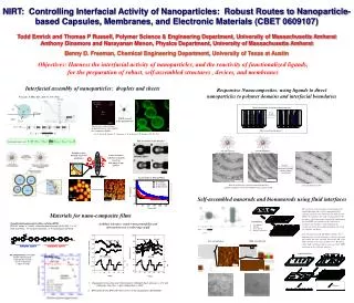
66 mm 50 mm 2 1 Choice of the best NDT for Trans-INDAnalysis of the components to inspect Beam sample Objective: Detect internal defects for Bridge Elements, in particular samples of the Beam and Deck, in composite material, on-site, for large areas • Characteristics of components: • High thickness (up to 66 mm) • Complex shapes • Sandwich structures (with lower core density, 40 kg/m3) Deck sample These characteristics limit the application of most common non destructive techniques
Choice of the best NDT for Trans-INDRequirements for the components to inspect large area of inspection high thickness of inspection Techniques fast Thickness of GFRP profile: 3-6 mm Thickness: Skin 8 mm Core 50 mm sandwich element inspection • Full field technique • Large area of inspection in one frame • Easy to use • Cost contained • It has the limit of thermal penetration (inspection depth: till 7-8 mm on CFRP) • Emissivity variation and external reflections affect the temperature pattern • Thermography
Choice of the best NDT for Trans-INDRequirements for the components to inspect • Full field technique • Large area of inspection in one frame • More sensitive to mechanic vibrations • Shaerography • The ultrasonic is the best technique to inspect high thickness and different materials • It can be applied adopting many configurations. • The use is limited in the case of complex shapes • Ultrasonics
Potential Technique Ultrasonic inspection Ultrasonic phase array • Advantages • Disadvantages • Commercialized transducers have frequencies higher than 500 kHz • Lower frequency probes require larger size of each element --> • Inspection of large areas • Curved shapes • Fast inspection - Decrease of resolution - Difficulty to realize complex shape - Difficulty to move on raw surface Air-coupled ultrasonic • large gap of acoustic impedance between the FRP and air • attenuation more than 150 dB on CFRP components • No energy passes through a sandwich with a foam core • non-contact • no problem with raw surface • no problem with curved shape • easiness of movement
Ultrasonic inspection Water-coupled • Advantages • Disadvantages • complex system for big components: • different degrees of freedom are possible • no problem with raw surface • potentially applicable on complex shapes • potentially applicable to inspect high thickness • big basin required • Anthropomorphic robot to move on complex shapes • difficult of apply off-site Classical contact ultrasonic • difficult to scan of raw surface • difficult of inspection on shapes with strong curvature. • inspection of high thickness components --> low frequency --> low resolution of the defect • potentially the best technique (pulse echo and trough transmission mode) to inspect high thickness elements. • High energy pass through the element
66 mm 50 mm Potential solutions for bridge elements with flexible installation and large area inspection Thermography for samples up to 7-8 mm in depth Laminate panels, monolithic elements Air-coupled ultrasonic – transmission mode up to 1-3 cm Contact ultrasonic – transmission mode over 3 cm • Ultrasonic with low frequency probes (100 kHz) need. • Air-coupled ultrasonic up to 15 mm in depth. • Contact ultrasonic probes in transmission mode are necessary for depth up to 15 mm. Sandwich with PUR Core
1° Case study - Sandwich sample • Characteristics/limits for inspection: • Sandwich structures • 2 skins in FRP (mix of Glass and Carbon Fibers) • 1 low density PUR core (40 kg/m3) • High thickness • Skin of about 8 mm • Core of about 50 mm • Complex shape • Curvilinear profile • Rough surface • Variable thickness • 50 mm • 66 mm Rough surface Technique of inspection: Contact Ultrasonic • Problems • To move the contact probe on rough surface. • To maintain the right coupling on bottom surface
Contact emitter probe Non-contact receiver probe The proposed inspection method Hybrid configuration • It generates a high energy ultrasound wave that travels through the element to be inspected • Low frequencies 100 kHz probe allows lower attenuation in high thickness components The emitter contact probe • It allows to have more freedom to follow the profile • It solves the problems of contact with bottom surface (coupled with water, oil, hanging) • It solves the problem to move on rough surfaces The non-contact receiver probe Equipment
Contact emitter probe with spherical cap Water Spherical cap Further improvement solution Further improvements, to overcome limits due to high curvature, rough surface and low spatial resolution, have been done. In experimental stage a thin spherical cap (1 mm) on the low frequency contact probe (100 kHz) has been applied. • The thin thickness and the cap filled with water reduce interferences on the wave transmitted • The use of spherical element has also the objective of focusing and amplifying the beam • To support the sphere design and optimization a numerical simulation has already started
50 cm 74 cm y x Defects Simulated defects Defects Core defect 10x3x30 mm Skin defect 10x2.5x30 mm The probes can be moved on the area of inspection by a Cartesian robot for planar shapes or by an anthropomorphic robot for complex shapes In this work a Cartesian robot has been used
Defects y x Detection sandwich component Hybrid configuration Core defect 10x3x30 mm; skin defect 10x2.5x30 mm without spherical cap with spherical cap SNR 19 dB SNR 13 dB Core defective area edge effect Skin Defective area artefact • In both cases the skin defect and core defect have been detected • In the map with spherical cap, the edge effects and artefacts are reduced • The signal to noise ration (SNR) is lower with spherical cap (13 dB) but still good enough to detect defects
Improvement of the flexibility Spherical cap - FEM simulation • Upgrade the spherical cap with the sphere to reduce the wear Pa • Study the possibility to have more efficiency with a focusing ultrasonic beam on the contact point by using a sphere ci Sphere system - FEM simulation ct Pa
Automation system • Glass fiber reinforced polymer • Small scale of the Beam • Monolithic element • Filament winding process • Pc to control the robot • Triggering the ultrasound signal • Plot in real time the two-dimensional and three-dimensional intensity scan map • Anthropomorphic robot for scan • Air-coupled ultrasound probes
Scan map of the glass fiber beam Automatic system which scans the total area of the component allowing a complete structural integrity control including internal defects 2D map of the ultrasound signal amplitude 3D map
IR 2nd Case study - Deck profile inspection Concrete Glass fiber reinforced polymer 3-6 mm of thickness Can be inspected using thermography techniques Hidden surface Ø 10 mm Ø 5 mm Ø 10 mm Ø 5 mm
Deck profile inspection IR load lamp Frame with the best contrast between the defective area and non defective area mirror To inspect hidden surfaces the solution can be the use of the mirror (aluminum) Thermal transient Non defective area Temperature (k) Defective area Frame Defects
Infrared scan system The scan system set up shows an anthropomorphic robot that move the infrared camera, a load lamp and a mirror Anthropomorphic robot Infrared camera Load lamp Acquisition system Sample of inspection
Scan system configuration The shape of the deck is complex and different configurations are request to inspect all deck surfaces Scan of bottom surface Scan of upper-left surface Scan of upper-right surface
Simulated defect to validate the inspection system Simulated defect has been introduced to validate the inspection system Defects: flat washers
Infrared images Infrared images showing defects obtained framing the surface opposite to the one where the flat washers are attached
Conclusions • Ultrasonic and thermography systems have been identified as the best techniques to inspect composite structural components for civil application due to their flexibility, cost and performances. • Innovative configuration such as hybrid ultrasonic and thermography with mirror have been studied to overcome the limits of inspection of complex structures. • A spherical cap has been applied on the ultrasonic transducer in order to increase the flexibility on curved profiles, rough surfaces and to improve the spatial resolution. • Thanks to the first promising experimental results, a numerical optimization of the spherical cap is in progress to optimize the system