Download
1 / 26
280 likes | 542 Views
The Integration and Test Program of the James Webb Space Telescope. Randy Kimble 1 Pamela Davila 1 , Charles Diaz 1 , Lee Feinberg 1 , Stuart Glazer 1 , Gregory Jones 2 , Rob Luetgens 2 James Marsh 1 , Gary Matthews 3 , Douglas McGuffey 1 , Pat O’Rear 4 , Deborah Ramey 1 ,

E N D
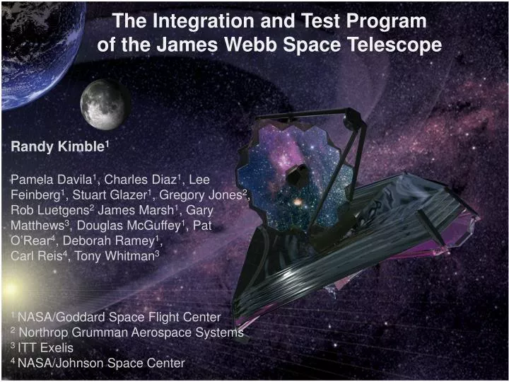
The Integration and Test Program of the James Webb Space Telescope Randy Kimble1 Pamela Davila1, Charles Diaz1, Lee Feinberg1, Stuart Glazer1, Gregory Jones2, Rob Luetgens2 James Marsh1, Gary Matthews3, Douglas McGuffey1, Pat O’Rear4, Deborah Ramey1, Carl Reis4, Tony Whitman3 1 NASA/Goddard Space Flight Center 2 Northrop Grumman Aerospace Systems 3 ITT Exelis 4 NASA/Johnson Space Center Presentation to: GSFC Code 600 staff
Agenda • Present a high level overview of the JWST integration and test program • What are we doing from now until 2018? • Highlight some of the particularly noteworthy activities in that flow and the status of the test hardware to support them • Such as some extremely challenging cryo-vacuum tests • Present some of the key goals of those tests • This is just the tip of the iceberg of the meticulous systems engineering efforts that track the verification of requirements and validation of models over the course of the program • Point out some of the ways in which we’re laying out the program to reduce the risk in the major tests (technical and cost/schedule) and to streamline those activities SPIE Astronomical Telescopes and Instrumentation: 8442-90
Philosophical Notes • As is typical, I&T for JWST is a hierarchical process • Lower level elements, developed and tested in parallel • Integrated into higher level assemblies and tested again • Subsystems → Science Instruments • Four Science Instruments + Electronics + Structure… → ISIM • ISIM + OTE → OTIS • OTIS + Spacecraft → Observatory • Verify performance requirements at the appropriate level of assembly • Try to catch problems at the lowest level possible (easiest to fix) • Provide independent cross-checks at the higher levels to confirm nothing went wrong in assembly • For an observatory as complex as JWST • There’s a lot of I…. • There’s a lot of T…. SPIE Astronomical Telescopes and Instrumentation: 8442-90
Launch N/A I&T Overview - Responsibilities ISIM I&T GSFC 29/SSDIF,15/SES,10 NIRCam OTIS I&T OTIS Ambient I&T OTIS Cryo I&T JSC 32 GSFC SSDIF, 10, 29 NIRSpec Exelis Support Exelis Support FGS NG Support NG Support OTE IPT OTE Optics Integration OTE Structures I&T MIRI NGST M8 GSFC 29/SSDIF Responsibility Execution Facility NASA NG NG / Exelis ESA / Ariane Sunshield IPT Observatory I&T Launch Site I&T Final Observatory I&T LV Integrated Operations Spacecraft Element I&T Spacecraft Bus I&T NGST M8, LATF, M1 Vibe CSG S5C, S5B, BAF, ZL3 NGST M8 NGST M8, M1 Vibe, M4 TV Sunshield I&T NGST M8 ISIM Support ISIM Support 4 SPIE Astronomical Telescopes and Instrumentation: 8442-90 6 July 2012
I&T of the Integrated Science Instrument Module (ISIM) • This activity is now well underway at GSFC, with the delivery to I&T of the ISIM structure, the first instrument (MIRI), and various electronics boxes (see Ray Lundquist’s talk later today) • A critical feature of the ISIM I&T program will be a series of cryo-vacuum tests in Goddard’s largest test chamber SPIE Astronomical Telescopes and Instrumentation: 8442-90
ISIM will be tested at ~35 K in the GSFC SES chamber using a cryogenic telescope simulator (OSIM) SES chamber (9m x 13m) LN2 Shroud GHe shroud ISIM OSIM Vibration Isolation Supports GHe shroud installation and test completed July 09 Fold Mirror 3 Tip/Tilt Gimbal Assembly OSIM Primary Mirror Alignment Diagnostic Module SPIE Astronomical Telescopes and Instrumentation: 8442-90
OTE Simulator (OSIM) with Beam Image Analyzer (BIA) Space System Development & Integration Facility (SSDIF) At NASA/Goddard Space Flight Center SPIE Astronomical Telescopes and Instrumentation: 8442-90
OSIM Is Currently Warming from Its 1st Cryo-Vac Test ISIM Test Platform (ITP) Photogrammetry Cameras BIA Upper GESHA He Shroud Region LN2 Shroud Region Vibration Isolators (3) SPIE Astronomical Telescopes and Instrumentation: 8442-90
OSIM Cryo-Vac Confirms Its Optical Performance • OSIM performed very well at temperature • A cryo run early in 2013 just before first ISIM cryo-vac will be required to complete its certification Beam Image Analyzer in the 30K section (top) OSIM in the 100K section (bottom) SPIE Astronomical Telescopes and Instrumentation: 8442-90
Key Aspects of the ISIM Cryo-Vac Program • The principal goals • Verify 6 degree-of-freedom alignment and pupil alignment of SI’s • Cross-check or verify SI image quality against OSIM • Verify wavefront sensing capabilities of the SI’s, obtain necessary calibrations • Verify thermal performance and correlate/validate thermal model • Verify performance with ISIM electrical systems, non-interference of SI’s with each other • Test ISIM operational scenarios, including the Onboard Script System • Trend SI performance SPIE Astronomical Telescopes and Instrumentation: 8442-90
Modifications to the Baseline ISIM I&T Flow • Baseline ISIM I&T • Receive fully qualified and fully calibrated Science Instruments • Perform mechanical and electrical integration to ISIM systems • Perform two ISIM cryo-vacs, bracketing the rest of the environmental test program (vibration, acoustics, EMC), demonstrating the stability of the optical and thermal performance against those environmental inputs • Various issues have arisen that dictate modifications to that baseline • Principal is the need to replace the detectors in the 3 NIR instruments with more robust versions that will not be available until 2014 • Delayed delivery of NIRSpec, flight MIRI Heat Exchanger Stage Assembly • Some NIRCam, NIRISS calibrations, verifications and one MIRI regression test have moved to ISIM level for greater efficiency SPIE Astronomical Telescopes and Instrumentation: 8442-90
Current ISIM I&T Plan • Detector delivery in 2014 gives a no-earlier-than date in 2015 for final “run for the record” ISIM cryo verification run • We still want to get started with ISIM cryo runs as soon as possible • ISIM cryo-vac will be an extremely complex and challenging test • Want to discover any issues with the test setup or procedures as early as possible • Retire the (low) risk of issues with the deferred SI verifications as early as possible • Hence the currently planned ISIM I&T flow has 3 cryo-vac tests • Cryo-1 – spring 2013; a “risk mitigation” run with 3 flight SI’s, NIRSpec ETU, and a non-flight MIRI Heat Exchanger Stage Assembly (HSA) • Cryo-2 – 2014; all flight SI’s, HSA, original detectors (baseline is still to have vibe/acoustics between to demonstrate optical/thermal stability) • Cryo-3 – 2015; ISIM verification run for the record with all flight elements including new detectors; vibe/acoustics required between cryo-2 and cryo-3 • Deliver fully qualified ISIM to OTIS (OTE + ISIM) integration; currently October 2015 (including ISIM-held margin) against need date of April 2016 SPIE Astronomical Telescopes and Instrumentation: 8442-90
Wings Cryo Diodes BP Harnesses PMBSS CJB CMU 20-21 Receiving Integration Test Prep & Shipping OTE Structure I&T @ NGAS Integrate Wing Hardware • Latch pads/catches • LRMs • Harnesses (W20,21,17,18) 06/2014 Transfer from ROF to VIS Wing Installation Wing Deployment Testing Remove PMBSS from STTARS Harness/ Cyro Diode Installation A • Route/Tape Diode harnesses • Install flight Diodes • Install flight PMBSS harnesses • Install flight OMNI harness • Wing offload GSE • Test LRMs actuated • Deployment Test • Repeatability Test • Alignment measurement • Deploy Wings • Install Wing lockout Clamps • Lift to ROF • Lift to OSS Cup up • VIS ( +V3) • Survey CS • Latch pads • Clamp wing to CS • Alignment meas. • Repeat as needed • Latch installation • Drive/ Passive hinges • MLI • Batwing • Rotate PMBSS to vertical • Separate HIF from ROF • Lift PMBSS w/ VLS (+V3) to VIS • Connect HIF to VIS 13 SPIE Astronomical Telescopes and Instrumentation: 8442-90 6 July 2012
OTE Structure I&T SMSS PTR Interceptor CTA DTA Integrate SMSS SMSS Deployment Test Integrate DTA DTA Deployment Test Integrate Mass Sims and PTR A B • OSS (-V1) • Install stowed DTA • Route Cooler Tower Assy. (CTA) • Alignment checks • Install OTE/IEC harnesses on DTA • (W33-41-46) • Install PTR -Interceptor Panel • ROF (+V3) • DTA upper to lower tube alignment • DTA lower tube alignment to “M” • Test LRM actuated • Powered Deploy/stow • Strain gage readout/preload • Lift to VIS • OSS (+V1) • Lift from FAJ using HLS • Install SMSS • Stow • Alignment meas. • Stow • Install LRMs • Repeatability Test • Install SMA MS • Lift to ROF • ROF (-V2) • Attach slant lines • Test LRMs actuated • Motorized deployment • Monitor SGs, Resolver, & load cells • Repeat as needed • Powered Stow • Re-engage LRM bolts • Remove slant lines • Lift to OSS • OSS (-V1) • Install PMSA MS • AOS MS • ISIM MS (offload) • HR MS • ISIM Rad MSs • PTR –Interceptor Pnl • V2 PTR MSs • Mass Props • Lift to ROF 14 SPIE Astronomical Telescopes and Instrumentation: 8442-90 6 July 2012
OTE Structure I&T STTARS C5-C Aircraft 04/06/15 Configure/ Ship to GSFC Stowed Modal Survey Deployed Modal Setup Deployed Modal Survey Remove Mass Simulators B • ROF (all orientations) • Cleaning operations • Install contamination covers & bags • Lift to Strongback • Install bag frame • Attach STTARS lid • Ship to GSFC • OSS (-V1) • Remove MS PTR, HR, PMSA, ISIM, AOS, & Radiators • Stow DTA & Wings (+V3) • Remove PTR Interceptor Panel • Mass Properties • OSS (+V1) OR • ROF (+V1) TBD • Measure OTE CG • Walkout SMSS • Dis-enage motor • Install Stinger • Setup SLV • VIS (+V3) • Install Accels • Snub DTA • Install stingers • Setup Scanning Laser Vibrometer (SLV) • Perform Test • Verify Results • Remove stingers, SLV • Deploy/Lockout Wings • Lift to ROF • Deploy DTA • Lift to OSS (TBD) • ROF (+V1) • Suspend w/ HLS • Perform Test • Suspend @ 2nd/3rd HPs • Perform Test • Verify Results • Stow SMSS • Remove SMA MS • Lift to OSS Cup down 15 SPIE Astronomical Telescopes and Instrumentation: 8442-90 6 July 2012
OTE Structure/Optics, ISIM Meet At GSFC for Ambient I&T • OTE structure and optics assembled in GSFC clean room on test stand above • ISIM then integrated to form OTIS (OTE + ISIM) • Vibe and acoustic tests at that level with pre- and post-test center of curvature measurements • Then off to JSC Ambient Optical Alignment Stand Complete Landing a primary mirror segment onto backplane simulator SPIE Astronomical Telescopes and Instrumentation: 8442-90
OTIS Testing in Historic Chamber A at JSC • Chamber Isolation • 1st unit tested Center of Curvature Optical Assembly (COCOA) Well into its I&T Suspension Subsystem 3 Autocollimating Flat Mirrors 1stunit complete. Units 2 & 3 polished Photogrammetry Windmills Space Vehicle Thermal Simulator (SVTS) w/ cryo-cooler and electronics AOS Source Plate Hardpoint Offloader Support System LN2 and Helium Cryogenic Shrouds and “barn door” SPIE Astronomical Telescopes and Instrumentation: 8442-90
Key Aspects of the JSC OTIS Cryo-Vac Program • Optical goals • Verify critical fixed alignments – ISIM to AOS • Verify co-alignment to within budgeted actuation range for active primary and secondary mirror • Verify optical performance stability against expected thermal transients • Cross-checks of lower level testing • Thermal goals • Demonstrate that the hardware reaches expected temperatures and verify performance there, including end-to-end performance of the MIRI cryo-cooler, which ranges from the warm spacecraft to the cold ISIM • Collect thermal balance point data that is used to correlate and validate the OTE/ISIM thermal flight model (highly sensitive to workmanship) • Electrical, operational goals • Proper electrical operation of flight systems, cross-strapping, redundancy • Demonstration of key operations, e.g. Wavefront Sensing & Control, parity checks of guiding functions • Day-in-the-life operational script testing • A critical overall goal is model validation SPIE Astronomical Telescopes and Instrumentation: 8442-90
JSC Chamber A Modifications Are Nearly Complete GHe Wall Shroud Jumper Installation GHe Door Shroud Installation After Air Flow Management System: Large Bore Pipe Cleaning Before SPIE Astronomical Telescopes and Instrumentation: 8442-90
JSC Chamber A Modifications Are Nearly Complete NITROGEN DISTRIBUTION Provide 80K to 358K LN2 to Shroud He Cold Box, Cryo Pumps 95% Complete – Installing final VJ Piping spools AIR FLOW MANAGEMENT Conditioning and Contamination Control of in-chamber air 85% Complete – Installing wiring and final large ducts HELIUM DISTRIBUTION Provide 15K to 333K gaseous He to the shroud 95% Complete – Installing final VJ Piping spools HELIUM SHROUD Provide 20 to 333 K environment to test article 100% Complete HIGH VACUUM SYSTEM Achieve 10-4 to ≤5x10⁻⁶ Torr 99% Complete – Installing final controls wiring NITROGEN SHROUD 90 To 358 K environment and pumping capacity 95% Complete – Performing leak/pressure checks POWER DISTRIBUTION Normal and Backup Power inside and outside chamber 95% Complete – Check outs ongoing RADIANT BARRIERS Shield Shrouds from chamber walls 99% Complete – Floor close-outs remaining RAIL SYSTEM Support Test Article in Highbay and Chamber (100% complete - in storage) SPIE Astronomical Telescopes and Instrumentation: 8442-90
Critical Optical GSE for OTIS Test Coming Along Very Well, Led By ITT Exelis Center of Curvature Optical Assembly (COCOA) • COCOA completed successful ambient optical testing and is well into cryo testing at MSFC • 1stAutoCollimating Flat Assembly is complete; 2nd and 3rd polished • Vibration isolator tested; confirmed that can be tuned in place • Photogrammetry cameras are based closely on those used with great success (30 μm accuracy) in ISIM structure cryo-tests SPIE Astronomical Telescopes and Instrumentation: 8442-90
JSC Test Facilities, GSE, Procedures Will Be Validated With Many Activities Before Flight OTIS Arrives 3/2014 7/2014 12/2014 Early 2017 11/2015 7/2015 3/2016 SPIE Astronomical Telescopes and Instrumentation: 8442-90 22
Pathfinder Cryo Tests Provide Invaluable Preparation OGSE-2 Pathfinder Thermal OGSE-1 PF Updated to be more Flight Like • Thermal GSE Checkout • (includes SVTS) • Dry run cooldown and warmup • Will allow risk reduction of some OTE Thermal Balance (design validation off the critical path) • Checkout Optical GSE that has not seen cryo before: CoC test, Hanging Config, Photogrammetry • No flight hardware except spares • Dynamics and Thermal Distortion portion of PF Augmentation occur here • Checkout Pass and a half test with flight AOS and GSE source plate system • Uses BIA (or BIA-like) camera as SI simulator 23 SPIE Astronomical Telescopes and Instrumentation: 8442-90
Risk Reduction/Streamlining of OTIS Cryo Test • Pathfinder test series (OGSE1, OGSE2, Pathfinder Thermal) validates hardware, procedures, trains personnel • Additional subsystem cryo tests mitigate risk of finding thermal problems in the JSC test • MIRI cryo-cooler I&T flow now includes an end-to-end performance test against flight-like loads (at one point JSC OTIS test was only cryo-cooler end-to-end verification) • “Core 2” test is now planned to update the earlier thermal test of “Core” region (where connections pass through sunshield from warm spacecraft to cold telescope) and validate the thermal model of that region before the JSC OTIS test • JSC OTIS cryo-test shortened substantially vs. early plans (~90 days vs. >160 days) • Many activities not requiring thermal stability folded into cooldown, warmup periods; other test procedures scrubbed for essentials • Pathfinder Thermal and Core 2 tests permit elimination of 2nd thermal balance point for savings of several weeks in cryo timeline SPIE Astronomical Telescopes and Instrumentation: 8442-90
Launch I&T Flow – Observatory (NG) Receive OTIS Integrate SCE and OTIS Ambient Test Dynamics Tests Post- Dynamics Deployments Post Dynamics Ambient Test Receive SCE • Mechanical Mate • Electrical Integration • Functional deployments • Observatory Alignments • CST-2 • EMC • GSEG-3 • Reinstall SA • Acceptance Acoustic • Accept. Sine Vibe • Separation Shock • GAA, SA, RS 1st Motion • SMSS 1st Motion • OTE Wing & DTA Deploy • SS Deploy, Fold & Stow • Deployed alignments • CST-3 • GSEG-4 • Stowed Alignments Receive LV PAF Mate to LV in BAF Fueling in S5B Configure Observatory in S5C Transport to CSG Limited Functional Test Mass Props & Ship Preps • Mass • Lateral CG • Move to container • By ship from Space Park to CSG • Rotate to vertical • Move into clean tent • Remove contamination bag • Post ship inspection • Limited Functional • GSEG End-To-End Test • Air Barge to S5B • Load propellants • Mate to LV PAF • Red Tag /Green Tag • CCU3 to BAF • Mate to LV • LVIF Test
Launch Summary • The Integration, Test, and Verification of a huge, cryogenic, segmented, deployable observatory is very challenging • A great deal of planning has been done for the many activities required, and the test equipment needed to support them is well into development • Great efforts will be made to streamline and reduce the risk (technical, cost/schedule) of the major activities • As always, flexibility is required in the I&T program to work around issues that arise and continue to make progress • We look forward to delivering a spectacular, well tested and verified observatory for launch in 2018 Presentation to: GSFC Code 600 staff