Download
1 / 31
310 likes | 459 Views
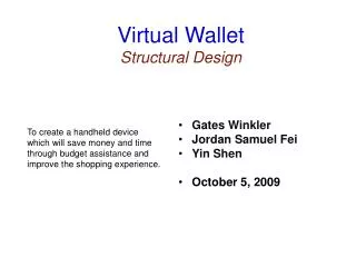
Virtual Wallet Design of BCD Binary Converters. Gates Winkler Jordan Samuel Fei Yin Shen October 19 , 2009. To create a handheld device which will save money and time through budget assistance and improve the shopping experience. Status. Finished Flow Chart Behavioral Verilog

E N D
Virtual WalletDesign of BCD Binary Converters • Gates Winkler • Jordan Samuel Fei • Yin Shen • October 19 , 2009 To create a handheld device which will save money and time through budget assistance and improve the shopping experience.
Status Finished • Flow Chart • Behavioral Verilog • Transistor Estimate • Floor Plan • Structure Proposal • Structural Verilog • Schematic To Do • Layout • Testing
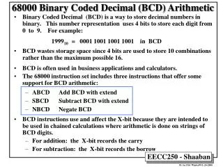
Introduction • Binary – Representing numbers on a “2” scale. • Ex. 19 = 10011 • BCD – Representing numbers on a “10” scale using a “2” scale. • Each set of 4 bits stores 1 base 10 digit. • Called a nibble. • Ex. 19 = 0001 1001 (2 nibbles) • 0001 = 1; 1001 = 9
When Converting • It is important to remember that though both are represented with 0 and 1s they will have different lengths when converted. • BCD bit length will always be a multiple of 4
Binary To BCD Algorithm • Assumes the necessary number of bits to store the nibbles are all initialized to 0. • Ex. Binary 51 = 110011 • Needs 2 nibbles all set to 0 => 0000 0000
Step 1 – Check For >=5 • Check all nibbles to see if any are >= 5. • 0000 < 5 • 0000 < 5 • If none are >= do nothing.
Step 2 – Shift Left • Shift all bits left shifting the MSB of the binary number into the LSB of the BCD number. Anything can be shifted in. • Initial: 0000 0000 : 110011 • After Shift: 0000 0001: 10011X
Step 3 – Repeat • Repeat x times where x = length of binary number. • 1 Run: 0000 0001: 10011X • 2 Run: 0000 0011: 0011XX • 3 Run: 0000 0110: 011XXX • Wait… After 3 runs there is a nibble that that is >= 5.
Step 1b – Greater or Equal 5 • If any nibbles are >= 5 then add 3 (0011) to that nibble. No nibble can ever be >9 so overflow is impossible. • 0000 < 5 • 0110 >5 thus • 0110 + 0011 = 1001 • After adding continue with step 2 • Initial: 0000 0110: 011XXX • After Increasing Nibbles: 0000 1001: 011XXX • After Shift: 0001 0010: 11XXXX
Step 3 – Repeat (Again) • Finish repeating. • 4 Run: 0001 0010: 11XXXX • 5 Run: 0010 0101: 1XXXXX • 6 Run After Adding: 0010 1000: 1XXXXX • 6 After Shifting: 0101 0001: XXXXXX • Final answer: 51 • 0101 = 5 • 0001 = 1
BCD To Binary Algorithm • Practically identical but reversed. Here are the changes. • Step 1 Shift • Shifts right instead of left • LSB of BCD is shifted into MSB of Binary • Must Shift in 0s • Step 2 Greater than/equal to 8 • Compares each BCD nibble to 8 instead. • If less than do nothing. • If greater than/equal subtract 3 from the nibble. • Step 3 Repeat (again) • Repeat x times where x = length of binary number.
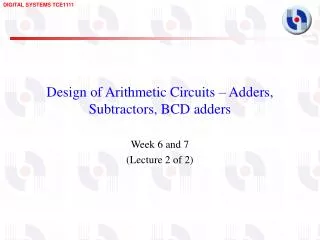
Structural • Binary To BCD • Needs 48 Flip Flops • 7 4-bit adders (28 1-bit adders) • 7 compare blocks. • BCD To Binary • Needs 48 Flip Flops • 7 4-bit subtracters (28 1-bit subtracters) • 7 compare blocks.
Flip Flops – Output • The Output Flip Flops can be regular Sequential Flip Flops.
Flip Flops – Input • The Input Flip Flops will be parallel Flip-Flops which allows us to chose whether we want to shift or write. • The nand gates allow for the flip flops to be written to on low write while it acts as a shifter on high write.
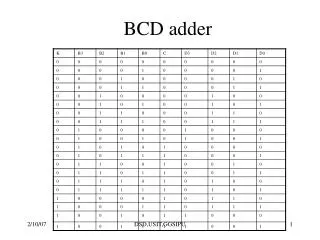
Compare to 5 Assumes 4 bit input B[3:0]. Use a Truth table to figure out block configuration
Compare to 8 • Easy, if Cin = 1 then the nibble will become 8 or greater. • Don’t need a compare.
Note • In a BCD – Binary converter the BCD is the input. Thus the Flip Flops are actually the ones shown on slide 13. • Binary Just Shifts without anything fancy. Just Needs respective Flip Flops.