Download
1 / 47
490 likes | 515 Views
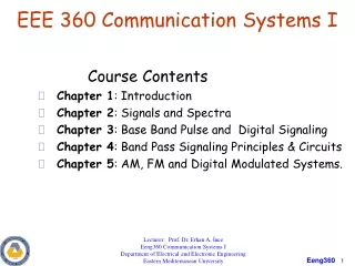
EEE 360 Energy Conversion and Transport. George G. Karady & Keith Holbert Chapter 4 Transmission Lines and cables. Lecture 6. 4.1 Construction. Transmission lines and cables. Extra-high-voltage lines Voltage: 345 kV, 500 kV, 765 kV Interconnection between systems High-voltage lines

E N D
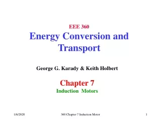
EEE 360 Energy Conversion and Transport George G. Karady & Keith Holbert Chapter 4 Transmission Lines and cables 360 Chapter 4 Transmission lines and cables
Lecture 6 360 Chapter 4 Transmission lines and cables
4.1 Construction 360 Chapter 4 Transmission lines and cables
Transmission lines and cables • Extra-high-voltage lines • Voltage: 345 kV, 500 kV, 765 kV • Interconnection between systems • High-voltage lines • Voltage: 115 kV, 230 kV • Interconnection between substations, power plants • Sub-transmission lines • Voltage: 46 kV, 69 kV • Interconnection between substations and large industrial customers • Distribution lines • Voltage: 2.4 kV to 46 kV, with 15 kV being the most commonly used • Supplies residential and commercial customers • High-voltage DC lines • Voltage: ±120 kV to ±600 kV • Interconnection between regions (e.g., Oregon-California) 360 Chapter 4 Transmission lines and cables
Transmission lines and cables • Three-phase conductors, which carry the electric current; • Insulators, which support and electrically isolate the conductors; • Tower, which holds the insulators and conductors; • Foundation and grounding; and • Optional shield conductors, which protect against lightning 360 Chapter 4 Transmission lines and cables
Transmission lines and cables 360 Chapter 4 Transmission lines and cables
Transmission lines and cables Distribution Line 360 Chapter 4 Transmission lines and cables
Transmission lines and cables 360 Chapter 4 Transmission lines and cables
Transmission lines and cables Definition of Parameters 360 Chapter 4 Transmission lines and cables
Transmission lines and cables 360 Chapter 4 Transmission lines and cables
Transmission lines and cables Connection diagram residential Concert conduit with cables in a manhole 360 Chapter 4 Transmission lines and cables
4.2 Components of transmission lines 360 Chapter 4 Transmission lines and cables
Transmission lines and cables Frequently used towers • Lattice tower, used for 220 kV and above; • Guyed lattice tower, 345 kV and above; • Tapered steel tube with cross-arm, 230 kV and below; • Concrete tower, for distribution and sub-transmission; and • Wood tower, for distribution to 220 kV 360 Chapter 4 Transmission lines and cables
Aluminum Conductor Steel Reinforced (ACSR); All Aluminum Conductor (AAC); and All Aluminum Alloy Conductor (AAAC). ACSR Coductor Transmission lines and cables 360 Chapter 4 Transmission lines and cables
Transmission lines and cables Insulators 360 Chapter 4 Transmission lines and cables
Transmission lines and cables Insulator Chain 360 Chapter 4 Transmission lines and cables
Transmission lines and cables Composite insulator. • (1) Sheds of alternating diameters prevent bridging by ice, snow and cascading rain. • (2) Fiberglass reinforced resin rod. • (3) Injection molded EPDM rubber weather sheds and rod covering. • (4) Forged steel end fitting, galvanized and joined to rod by swaging process. (Source: Sediver, Inc., York, SC) 360 Chapter 4 Transmission lines and cables
Transmission lines and cables • (1) is the clevis ball, • (2) is the socket for the clevis, • (3) is the yoke plate, and • (4) is the suspension clamp. (Source: Sediver) • Figure 4.15 Line post-composite insulator with yoke holding two conductors. 360 Chapter 4 Transmission lines and cables
4.3 Cables 360 Chapter 4 Transmission lines and cables
Transmission lines and cables Figure 4.16 Single-phase high-voltage cable with solid dielectric 360 Chapter 4 Transmission lines and cables
Transmission lines and cables Figure 4.17 Three-phase distribution cable with solid dielectric. 360 Chapter 4 Transmission lines and cables
4.4 Transmission Line Electrical Parameters 360 Chapter 4 Transmission lines and cables
Transmission lines and cables Table 4.1 ACSR cable technical data 360 Chapter 4 Transmission lines and cables
Transmission line parameter Resistance Ohm/mile Table 4.1 Inductance Henry/mile Equation Capacitance Farad/mile Equation Transmission lines and cables 360 Chapter 4 Transmission lines and cables
Transmission lines and cables Data from the Table 4.1 • Name Bird name Kiwi • Conductor Diameter • Resistance at 50C or 75C • Geometrical Mean Radius (GMR) 360 Chapter 4 Transmission lines and cables
Transmission lines and cables Data needed for calculation • Transmission line length • Number of conductor / Bundle • Conductor diameter and GMR • Distance between phases • Conductor height 360 Chapter 4 Transmission lines and cables
Transmission lines and cables Typical transmission line • Horizontal arrangement • Two ground conductors • Two conductors per bundle 360 Chapter 4 Transmission lines and cables
Transmission lines and cables Resistance • Stranding increase resistance • Increases by temperature • Increases by skin effect • AC resistance higher than DC • Accurate value from Table 4.1 360 Chapter 4 Transmission lines and cables
Transmission lines and cables Capacitance Two-conductor bundle Three-conductor bundle Four-conductor bundle: 360 Chapter 4 Transmission lines and cables
Transmission lines and cables Inductance 4.31 Transposed line Two-conductor bundle Three-conductor bundle Four-conductor bundle: 360 Chapter 4 Transmission lines and cables
Transmission lines and cables Inductance/Capacitance 360 Chapter 4 Transmission lines and cables
Transmission lines and cables Inductance/Capacitance 4.31 Transposed line Two-conductor bundle Three-conductor bundle Four-conductor bundle: 360 Chapter 4 Transmission lines and cables
Numerical exerciseTransmission lines Parameter calculation MATCAD 360 Chapter 4 Transmission lines and cables
Transmission lines Parameter calculation MATCAD D 360 Chapter 4 Transmission lines and cables
Transmission lines Parameter calculation MATCAD 360 Chapter 4 Transmission lines and cables
Transmission lines Parameter calculation MATCAD 360 Chapter 4 Transmission lines and cables
Transmission lines Parameter calculation MATCAD 360 Chapter 4 Transmission lines and cables
Equivalent circuit 360 Chapter 4 Transmission lines and cables
Transmission lines Parameter calculation MATCAD 360 Chapter 4 Transmission lines and cables
Transmission lines and cables Figure 4.50 Equivalent network of a short line. 360 Chapter 4 Transmission lines and cables
Transmission lines and cables Figure 4.49 Equivalent network of a medium-length line. 360 Chapter 4 Transmission lines and cables
j X IS R Ir ICR Ics I VS VR C/2 C/2 Transmission lines and cables Figure 4.49 Equivalent network of a medium-length line. 360 Chapter 4 Transmission lines and cables
Numerical exerciseTransmission lines Loading MATCAD 360 Chapter 4 Transmission lines and cables
Transmission lines and cables • Steps of calculation (4.5.1.3) • Given data: • The power is variable, selected value is: • Load current calculation: 360 Chapter 4 Transmission lines and cables
Transmission lines and cables • Steps of calculation (4.5.1.3) • Capacitive current: • Line current • Supply voltage: 360 Chapter 4 Transmission lines and cables
Transmission lines and cables • Steps of calculation (4.5.1.3) • Capacitive current: • Supply/network current 360 Chapter 4 Transmission lines and cables
Transmission lines and cables Figure 4.48 Equivalent network for a long transmission line. 360 Chapter 4 Transmission lines and cables