Download
1 / 43
430 likes | 434 Views
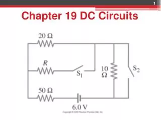
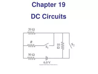
Chapter 26 DC Circuits. 26-2 Resistors in Series and Parallel. Example 26-8 : Analyzing a circuit.

E N D
26-2 Resistors in Series and Parallel Example 26-8: Analyzing a circuit. A 9.0-V battery whose internal resistance r is 0.50 Ω is connected in the circuit shown. (a) How much current is drawn from the battery? (b) What is the terminal voltage of the battery? (c) What is the current in the 6.0-Ω resistor?
Multiple configurations Assume that in each circuit the battery gives 12 V and each resistor has a resistance of 4 ohms. In which circuit does the largest current flow through the battery? (e) All equal
Multiple configurations Assume that in each circuit the battery gives 12 V and each resistor has a resistance of 4 ohms. In which circuit does the largest current flow through the battery? What is that current?
Multiple configurations Assume that in each circuit the battery gives 12 V and each resistor has a resistance of 4 ohms. In which circuit does the largest current flow through the battery? What is that current?
Circuit Maze If each resistor has a resistance of 4 and each battery is a 4 V battery, what is the current flowing through the resistor labelled “R”? (a) 0 A (b) 2 A (c) 4 A (d) 8 A (e) 16 A
Circuit Maze If each resistor has a resistance of 4 and each battery is a 4 V battery, what is the current flowing through the resistor labelled “R”? (a) 0 A (b) 2 A (c) 4 A (d) 8 A (e) 16 A
R5 R2 R3 R1 R4 V 1) R1 2) both R1and R2 equally 3) R3and R4 4) R5 5) all the same ConcepTest 26.6Even More Circuits Which resistor has the greatest current going through it? Assume that all the resistors are equal.
R5 R2 R3 R1 R4 V 1) R1 2) both R1and R2 equally 3) R3and R4 4) R5 5) all the same ConcepTest 26.6Even More Circuits Which resistor has the greatest current going through it? Assume that all the resistors are equal. The same current must flow through the left and right combinations of resistors. On the LEFT, the current splits equally, so I1 = I2. On the RIGHT, more current will go through R5 than R3+ R4, since the branch containing R5 has less resistance. Follow-up:Which one has the smallest voltage drop?
ConcepTest 26.8a Lightbulbs 1)the 25 W bulb 2)the 100 W bulb 3)both have the same 4) this has nothing to do with resistance Two lightbulbs operate at 120 V, but one has a power rating of 25 W while the other has a power rating of 100 W. Which one has the greater resistance?
ConcepTest 26.8a Lightbulbs 1)the 25 W bulb 2)the 100 W bulb 3)both have the same 4) this has nothing to do with resistance Two lightbulbs operate at 120 V, but one has a power rating of 25 W while the other has a power rating of 100 W. Which one has the greater resistance? Since P = V2 / R,the bulb with the lower power rating has to have the higher resistance. Follow-up: Which one carries the greater current?
26-3 Kirchhoff’s Rules Some circuits cannot be broken down into series and parallel connections. For these circuits we use Kirchhoff’s rules.
26-3 Kirchhoff’s Rules Junction rule: The sum of currents entering a junction equals the sum of the currents leaving it (i.e., charge does not pile up).
26-3 Kirchhoff’s Rules Loop rule: The sum of the changes in potential around a closed loop is zero.
26-3 Kirchhoff’s Rules • Problem Solving: Kirchhoff’s Rules • Label each current, including its direction; don’t worry if you get the direction wrong. The math will take care of it. • Identify unknowns. • Apply junction and loop rules; you will need as many independent equations as there are unknowns. Each new equation MUST include a new variable. • Solve the equations, being careful with signs. If the solution for a current is negative, that current is in the opposite direction from the one you have chosen.
26-3 Kirchhoff’s Rules • Example: Using Kirchhoff’s rules. • Calculate the currents (call them I1, I2, and I3) through the three batteries of the circuit in the figure. • What is Va-Vb?
26-3 Kirchhoff’s Rules Note: Potential change negative in specified direction of current. Potential change positive in specified direction opposite to current.
1 I2 2 6 V 2 V 2 V 4 V I3 I1 1 3 ConcepTest 26.12 Kirchhoff’s Rules 1) 2 – I1 – 2I2 = 0 2) 2 – 2I1 – 2I2– 4I3= 0 3) 2 – I1 – 4 – 2I2= 0 4) I3 – 4 – 2I2 + 6= 0 5) 2 – I1 – 3I3– 6= 0 Which of the equations is valid for the circuit below?
1 I2 2 6 V 2 V 2 V 4 V I3 I1 1 3 ConcepTest 26.12 Kirchhoff’s Rules 1) 2 – I1 – 2I2 = 0 2) 2 – 2I1 – 2I2– 4I3= 0 3) 2 – I1 – 4 – 2I2 = 0 4) I3 – 4 – 2I2 + 6= 0 5) 2 – I1 – 3I3– 6= 0 Which of the equations is valid for the circuit below? Eq. 3 is valid for the left loop: The left battery gives +2 V, then there is a drop through a 1 W resistor with current I1 flowing. Then we go through the middle battery (but from + to – !), which gives –4 V. Finally, there is a drop through a 2 W resistor with current I2.
26-4 Series and Parallel EMFs; Battery Charging EMFs in series in the same direction: total voltage is the sum of the separate voltages.
26-4 Series and Parallel EMFs; Battery Charging EMFs in series, opposite direction: total voltage is the difference, but the lower-voltage battery is charged.
26-4 Series and Parallel EMFs; Battery Charging EMFs in parallel only make sense if the voltages are the same; this arrangement can produce more current than a single emf.
26-5 Circuits Containing Resistor and Capacitor (RC Circuits) When the switch is closed, the capacitor will begin to charge. As it does, the voltage across it increases, and the current through the resistor decreases.
26-5 Circuits Containing Resistor and Capacitor (RC Circuits) To find the voltage as a function of time, we write the equation for the voltage changes around the loop: Since Q = dI/dt, we can integrate to find the charge as a function of time:
26-5 Circuits Containing Resistor and Capacitor (RC Circuits) The voltage across the capacitor is VC = Q/C: The quantity RC that appears in the exponent is called the time constant of the circuit:
26-5 Circuits Containing Resistor and Capacitor (RC Circuits) Example 26-11: RC circuit, with emf. The capacitance in the circuit shown is C = 0.30 μF, the total resistance is 20 kΩ, and the battery emf is 12 V. Determine (a) the time constant, (b) the maximum charge the capacitor could acquire, (c) the time it takes for the charge to reach 99% of this value, (d) the current I when the charge Q is half its maximum value, (e) the maximum current, and (f) the charge Q when the current I is 0.20 its maximum value.
26-5 Circuits Containing Resistor and Capacitor (RC Circuits) If an isolated charged capacitor is connected across a resistor, it discharges: Capacitor, NOT battery!
26-5 Circuits Containing Resistor and Capacitor (RC Circuits) Example 26-12: Discharging RC circuit. In the RC circuit shown, the battery has fully charged the capacitor, so Q0 =CE. Then at t = 0 the switch is thrown from position a to b. The battery emf is 20.0 V, and the capacitance C = 1.02 μF. The current I is observed to decrease to 0.50 of its initial value in 40 μs. (a) What is the value of Q, the charge on the capacitor, at t = 0? (b) What is the value of R? (c) What is Q at t = 60 μs?
26-5 Circuits Containing Resistor and Capacitor (RC Circuits) Conceptual Example 26-13: Bulb in RC circuit. In the circuit shown, the capacitor is originally uncharged. Describe the behavior of the lightbulb from the instant switch S is closed until a long time later.
26-6 Electric Hazards Most people can “feel” a current of 1 mA; a few mA of current begins to be painful. Currents above 10 mA may cause uncontrollable muscle contractions, making rescue difficult. Currents around 100 mA passing through the torso can cause death by ventricular fibrillation. Higher currents may not cause fibrillation, but can cause severe burns. Household voltage can be lethal if you are wet and in good contact with the ground. Be careful!
26-6 Electric Hazards A person receiving a shock has become part of a complete circuit.
26-6 Electric Hazards The safest plugs are those with three prongs; they have a separate ground line. Here is an example of household wiring – colors can vary, though! Be sure you know which is the hot wire before you do anything.
26-7 Am-, Volt-, and Ohm-meters An ammeter measures current; a voltmeter measures voltage. Both are based on galvanometers, unless they are digital. The current in a circuit passes through the ammeter; the ammeter should have low resistance so as not to affect the current.
26-7 Am-, Volt-, and Ohm-meters Example 26-15: Ammeter design. Design an ammeter to read 1.0 A at full scale using a galvanometer with a full-scale sensitivity of 50 μA and a resistance r = 30 Ω. Check if the scale is linear.
26-7 Am-, Volt-, and Ohm-meters A voltmeter should not affect the voltage across the circuit element it is measuring; therefore its resistance should be very large.
26-7 Am-, Volt-, and Ohm-meters Example 26-16: Voltmeter design. Using a galvanometer with internal resistance 30 Ω and full-scale current sensitivity of 50 μA, design a voltmeter that reads from 0 to 15 V. Is the scale linear?
26-7 Am-, Volt-, and Ohm-meters Summary: An ammeter must be in series with the current it is to measure; a voltmeter must be in parallel with the voltage it is to measure.
26-7 Am-, Volt-, and Ohm-meters An ohmmeter measures resistance; it requires a battery to provide a current.
Summary of Chapter 26 • A source of emf transforms energy from some other form to electrical energy. • A battery is a source of emf in parallel with an internal resistance. • Resistors in series:
Summary of Chapter 26 • Resistors in parallel: • Kirchhoff’s rules: • Sum of currents entering a junction equals sum of currents leaving it. • Total potential difference around closed loop is zero.
Summary of Chapter 26 • RC circuit has a characteristic time constant: • To avoid shocks, don’t allow your body to become part of a complete circuit. • Ammeter: measures current. • Voltmeter: measures voltage.