Download
1 / 7
70 likes | 163 Views
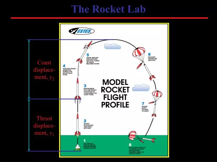
The Rocket Lab. Coast displace-ment, y 2. Thrust displace-ment, y 1. The Engine. Thrust “profile” of the Estes A8-3 rocket engine.

E N D
The Rocket Lab Coast displace-ment, y2 Thrust displace-ment, y1
The Engine Thrust “profile” of the Estes A8-3 rocket engine The Estes A8-3 engine has an average thrust force of 4 newtons, an impulse of 2.50 Ns, a thrust time of 0.6 seconds, and a delay of 3 seconds for the ejection charge.
Measured Altitude Step 1: During launch your classmates will measure the launch angle from two positions, A and B, on a baseline of known length. The measured altitude is found with trigonometry. Three measurements will be taken from each position. We will launch at the middle of the football field, with angles measured from opposite corners of each end zone. How long is the baseline, AB, in meters, if the football field is 160 feet wide, and 360 long?
Predicted Altitude List of Variables
Predicted Altitude Determining rocket’s mass Step 2: During flight the rocket continuously changes (loses) mass as it burns propellant, tracking smoke, and ejection charge. Each rocket has it own mass based on model type, glue, paint, etc., but the engines are virtually identical. Masses m1, m2, and m3 can now be determined based on your rocket’s mass.
Predicted Altitude Thrust Stage - Finding thrust displacement y1 Step 3: For the thrust stage we consider three impulses exerted on the rocket and relate those impulses to the change in momentum of the rocket. Step 4: The impulses will result in a change in momentum for the rocket. Since the rocket starts at rest this change in momentum is the final momentum. Solve for v1 Step 5: Using kinematics the final rocket velocity v1 can be related to the thrust distance y1. Remember that the rocket starts from rest. Solve for y1
Predicted Altitude Coast Stage - Finding coast displacement y2 Step 6: For the coast stage we consider energy conservation. When coasting begins, the rocket has kinetic energy and potential energy (above the ground). If we move the reference level for GPE to y1 then GPE = 0 as coasting begins. Step 7: During coast, the rocket converts kinetic energy into more potential energy and heat energy. Solve for y2 Total predicted altitude y1 + y2 Step 8: Now the total predicted altitude is easily found by adding positions y1 and y2. You will compare this to the measured altitude in the conclusion of the lab.