Download
1 / 19
190 likes | 288 Views
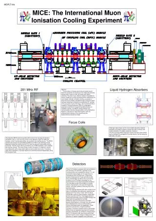
Progress in the construction of the MICE cooling channel and first measurements. Adam Dobbs, EPS-HEP, 23 rd July 2011. Outline. Motivation: Neutrino Factory and Muon Collider Ionisation Cooling The MICE Experiment The Beamline – rate and emittance measurements Cooling channel status

E N D
Progress in the construction of the MICE cooling channel and first measurements Adam Dobbs, EPS-HEP, 23rdJuly 2011
Outline • Motivation: Neutrino Factory and Muon Collider • Ionisation Cooling • The MICE Experiment • The Beamline – rate and emittance measurements • Cooling channel status • Conclusion A. Dobbs EPS-HEP 2011
Muon Collider Muon Collider Motivation Neutrino Factory • Neutrino Factory: Best coverage of the oscillation parameter space of any proposed next generation oscillation experiment. • Muon Collider: route to multi – TeV lepton – anti-lepton collisions. • Both types of muon accelerator with technology synergies: • Intense proton driver • Complex target • Muons from pion decay → Large initial emittance → Muon Cooling A. Dobbs EPS-HEP 2011
Muon Ionisation Cooling • Traditional beam cooling techniques are too slow due to the short muon lifetime (2.2 µs at rest) • Leads to concept of ionisation cooling • Beam momentum is reduced in all directions by passing beam through an absorber (cooling) • Beam is re-accelerated in longitudinal direction (sustainable cooling) → Emittance reduction A. Dobbs EPS-HEP 2011
The MICE Experiment • The international Muon Ionisation Cooling Experiment • Demonstrate muon ionisation cooling for application to a Neutrino Factory or Muon Collider • Produce a 10% emittance reduction, measured to1% accuracy (hence requiring an absolute emittance measurement of 0.1%) A. Dobbs EPS-HEP 2011
ISIS MICE Hall R5.2 Location (Mousehole) Hosted at the Rutherford Appleton Laboratory, U.K. Proton driver provided by the ISIS 800MeV proton synchrotron ISIS MICE Hall A. Dobbs EPS-HEP 2011
MICE Steps µ Step I Commission beam line & detectors - achieved! Step IV Precisely measure emittance reduction - Q3 2012 Step V Sustainable cooling - Q2 2014* Step VI Full cooling channel * Target date to run Step V before ISIS long shutdown from Aug 2014 – Feb 2015 A. Dobbs EPS-HEP 2011
Beamline status • Step I achieved – MICE Muon Beamline producing beam since Spring 2008 • Target: cylindrical titanium target pulsed into ISIS using stator drive • Magnets: 3 quadrupole triplets and 2 dipoles installed and operational • Decay Solenoid (DS): 5T superconducting DS installed and operational • Time-Of-Flight (TOF): 3 TOF stations commissioned and performing well • Luminosity monitor: commissioned and performing well • CKOVs, Electron Muon Ranger (EMR) and KLOE-Light (KL) undergoing commissioning A. Dobbs EPS-HEP 2011
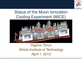
The MICE Beamline A. Dobbs EPS-HEP 2011
0.40 m 0.42 m TOF0 10 x 40mm scint. bars sx = 11.5mm 7 x 60mm bars sx = 17.3mm TOF1 TOF Detectors • 3 stations, each with 2 orthogonal layers of scintillator bars • Provides spatial as well as timing information Beam profile using TOF station (Spatial res. can be increased by use of timing information) [The design and commissioning of the MICE upstream time-of-flight system, R. Bertoni et al. , NIM-A 615 (2010) 14-26] A. Dobbs EPS-HEP 2011
Particle Identification µ µ (backward) (forward) π e e dt (ns) dt (ns) • Particle Identification (PID) from TOF • Good clean muon beam achieved when optics set for π→µtransport (right histogram) – exploits emitted muon direction with dipoles to remove pions • Additional π, µseparation using CKOVs and Electron Muon Ranger (in commissioning) A. Dobbs EPS-HEP 2011
Particle Rates • Systematically study ISIS beam loss induce by MICE target and subsequent particle rate • Observe linear increase of particle rate with beam loss • Observe ~10 per 3.2ms spill at 2V.ms beam loss in µ- (typical current running point) • Dependent on beam optics µ- A. Dobbs EPS-HEP 2011
TOF0 TOF1 Emittance measurement technique • Emittance normally measured using three beam profile measurements • As transfer matrix Mij = Mij(pz) this is not possible on MICE due to large pzspread • New technique developed on MICE (M. Rayner) to measure emittance using two TOF stations while waiting for the trackers: • Measure x, y, t at both TOF0 and TOF1 • Identify muons using time-of-flight • Momentum-dependent transfer matrices map particle motion from TOF0 to TOF1 through drifts and quads • Make initial estimate of path length and pz, then use pzand transfer map to improve path length estimate, then recalculate pz. Iterate until converges. • Calculate x’= px/ pzand y’ = py / pzat TOF0 and TOF1 • Compare with simulation (x0,y0) (x1,y1) [Upcoming MICE Step I paper will describe technique in detail] A. Dobbs EPS-HEP 2011
Emittance Results • Using a standard (6mm, 200 MeV/c) µ– beam: MC truth MC reconstruction Data • Measure εx= 2.94mm and εy= 1.15mm for this beam. Transverse normalised emittance is then given approximately by εn≈ ( pz / mµ ) √(εx εy) • Numerous other beams (generated by beamline optics) measured covering MICE emittance – momentum matrix, giving emittance and twiss parameters A. Dobbs EPS-HEP 2011
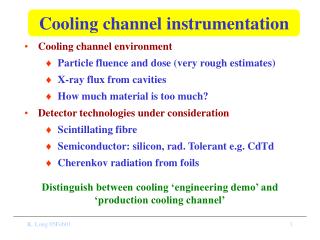
Cooling channel status • Scintillating fibre trackers built and taking cosmic data • Spectrometer solenoids, absorbers and RF cavities under construction 4T Spectrometer Solenoid II Absorber Focus Modules 4T Spectrometer Solenoid I µ Tracker II 201 MHz RF Cavities Tracker I A. Dobbs EPS-HEP 2011
Trackers and Diffuser • 2 trackers, 5 stations per tracker, 3 planes of 350µm scintillating fibres per plane • Measures x, x’, y, y’, pz • Measured track residual 650µm with 470µm point resolution (c.f. TOFs) • Constructed & ready taking cosmic data • 4T superconducting spectrometer solenoids still in production for Step IV • Diffuser used to expand beam emittance prior to cooling • 4 stacked disks of varying thickness • Camera iris design Actuators Irises Optical sensors A. Dobbs EPS-HEP 2011
Absorbers and RF Coupling Coils • 2 RFCC stations • Curved beryllium windows • Restores longitudinal momentum lost in absorbers, via 201.25 MHz 8 MV/m RF field • 3 Absorber Focus Modules • Use LH2 as absorber and also LiH (plastic also possible later) • Use magnetic field to guide muons (4T in solenoid mode) A. Dobbs EPS-HEP 2011
Summary • Ionisation cooling a necessary technology for any future Neutrino Factory or Muon Collider – MICE to demonstrate the technique • MICE Muon Beamline successfully commissioned – Step I of MICE achieved • First preliminary measurements of emittance performed using the excellent TOF detectors • Progress continues on fabrication of cooling channel components • Goal to measure muon cooling in 2012 and sustainable muon cooling in 2014 A. Dobbs EPS-HEP 2011
Questions? Thanks for your attention. Questions? A. Dobbs EPS-HEP 2011