Download
1 / 23
240 likes | 429 Views
0.0. 0.0. Durable. Unit 13/Chapter 18 Electric Currents. “Motion” of Positive Charges. Many texts define current as the direction that the “positive” charges move; however, there are not actually any “positive” charges that contribute to current flow.

E N D
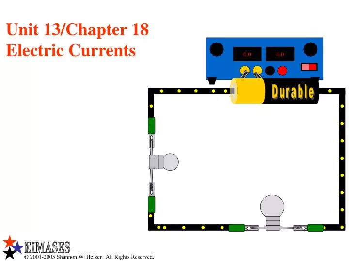
0.0 0.0 Durable Unit 13/Chapter 18Electric Currents
“Motion” of Positive Charges • Many texts define current as the direction that the “positive” charges move; however, there are not actually any “positive” charges that contribute to current flow. • The “positive” charges are actually holes vacated by electrons which do actually move and form current. • These holes may be thought of as positive charges; however, they do not move as they are “anchored” within the material. • Electrons move when a potential difference is applied across a conductor. • As an electron moves leaving behind a hole, another electron occupies the hole left behind by the first electron. • When this electron occupies this hole, it leaves behind another hole and the process repeats. • The positive charges appear to move; however, it is the electrons that actually move. • However, due to a long standing tradition in physics, we will select the opposite direction as that which the electrons actually move to be our current direction..
Conduction Electrons • In organic compounds, electrons are bound to specific atoms. • In metallic compounds, some of the electrons are not bound to a specific atom. • They are free to move throughout the metal. • These electrons are called conduction electrons. • If a potential difference is placed across the wire (like when you connect the wire to a battery), then the electrons will move. • As they move, the electrons collide with the metallic atoms. • Depending upon the number of collisions an electron has, it may move faster or slower through the metallic structure. • Remember, moving electrons in a wire are known as current.
Durable Batteries and Current • A complete circuit is one that connects a battery to an electrical component back to a battery. • Remember, electrons flow from the negative end of a battery through the light bulb (resistor) and back into the positive end of the battery. • By our standard, the current flows in the opposite direction. • The symbol “I” is used to denote current. • Current is the number of electrons passing a certain point in a circuit per unit of time. I
Durable Resistors • Resistors are used to control the amount of current flowing through a circuit. • Resistors impede the flow of electrons (current). • They impede this flow because certain electrical items have maximum limitations on the current they can handle. • Consider the Light Emitting Diode (LED) in the figure to the right. • The battery supplies too high a current to the LED. • As a result, the LED is damaged by the current. • When a resistor is placed into the circuit, the current is reduced to a level appropriate for use with the LED, and the LED is not damaged.
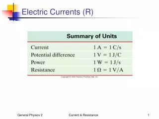
Ohm’s Law • Ohm’s Law gives us a mathematical expression relating the voltage (V), Current (I), and Equivalent Resistance (R) of a circuit. • The three forms of Ohm’s Law are listed below. • In this equation, R is the Resistance in Ohms (), I is the Current in Amps (A), and V is the Voltage in Volts (V).
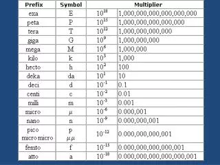
Resistance and Resistivity • The resistance of a material is dependant on the resistivity of the material. • This relationship is expressed by Pouillet's law. • In this equation, R is the resistance in Ohms (), is the resistivity in Ohm meters (m), L is the length in meters (m), and A is the cross sectional area in square meters (m2). • The values of resistivity for different materials may be found on page 501 of your textbook.
Resistance and Resistivity • Suppose a wire of length L and area A (assume a circular cross section) has a resistance of R1. • How much resistance (R2) would a second wire, made from the same material, have if its length was 2L?
Resistance and Resistivity • Suppose a wire of length l and area A (assume a circular cross section) has a resistance of R1 (in terms of the wire’s diameter). • How much resistance would a second wire, made from the same material, have if its diameter was halved (d2 = d1/2)?
Power Equation • Power is the rate at which electrical energy is consumed. • The equation used to determine power consumption is as shown. • This equation is used to calculate the Power consumed in Watts (W) by a resistor when the current and the voltage drop across the resistor are known. • Using Ohm’s Law, derive two more forms of the power equation.
0.0 0.0 Durable Direct Current v. Alternating Current • In a direct current circuit (one with a battery) the electrons flow in one and only one direction. • In an alternating current circuit (like the electricity from your wall outlet), the electrons repetitively change directions. • Either way, the light remains lit because the electrons still move through it.
Direct Current • Batteries produce direct current (DC). • The graph below shows a plot of a direct current produced by a battery.
Alternating Current • Your home uses Alternating Current (AC). • This current is produced by generators in electrical power plants. • The graph below shows a plot of a alternating current.
Electrical Safety: Fuse • Two devices are used in household and vehicle applications in order to ensure electrical safety: a fuse and a circuit breaker. • When the current through the fuse pictured below exceeds a certain value, the metallic ribbon melts and opens the circuit. • A fuse must be replaced after preventing an electrical overload.. Metallic Ribbon
Electrical Safety: Circuit Breaker • When the current through a circuit breaker exceeds a certain value, it opens the circuit. • A circuit breaker can be flipped back on and does not need to be replaced. Bi-Metallic Strip
Durable Durable Durable Durable Sure Start Batteries • Batteries come in many shapes and sizes that have a variety of voltage and currents. • Identify the voltages of the four common battery types shown below.
Durable Batteries • This slide will explain how a battery provides electricity for use in your small electrical appliances. • Free electrons and “holes,” which are the absences of electrons, are produced within the battery due to electrochemical reactions.
Durable Durable Durable Durable Series Battery Configuration WS 6 #15-18 • Batteries, like other electrical components, may be connected in series or parallel configurations. • In a series configuration like the one below, the electrons flow from one battery into the next battery where they remain. • As a result, the current produced by combining batteries in series is equal to the current produced by just one of the batteries. • However, when batteries are connected in series, the voltages (electric potentials) are added. • What is the voltage produced by the four AA batteries shown below? • These four batteries each produce 1.5 V; therefore, the total voltage produced by these batteries is 6.0 V.
Durable Durable Durable Durable Parallel Battery Configuration WS 6 #15-18 • Notice what happens to the current when batteries are connected in parallel. • The current produced by parallel batteries combines resulting in a higher current. • AA batteries typically provide 500 mA. • What is the total current produced by the batteries below? • 2000 mA. • What is the total voltage of these four batteries? • The voltage is the same as that of a single battery. • The schematic diagram for these batteries would be as follows.
EIMASES This presentation was brought to you by Where we are committed to Excellence In Mathematics And Science Educational Services.
Durable Durable Durable Durable Durable Durable Durable Durable