Download
1 / 26
260 likes | 395 Views
MuCool RF Program. 805 and 201 MHz Studies. RF Cavity R and D. ANL/FNAL/IIT/LBNL/UMiss/Cockcroft. MuCool Test Area. Facility to test all components of cooling channel (not a test of ionization cooling) At high beam power Designed to accommodate full Linac Beam 1.6 X 10 13 p/pulse @15 Hz

E N D
MuCool RF Program 805 and 201 MHz Studies
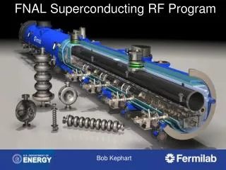
RF Cavity R and D ANL/FNAL/IIT/LBNL/UMiss/Cockcroft
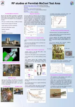
MuCool Test Area • Facility to test all components of cooling channel (not a test of ionization cooling) • At high beam power • Designed to accommodate full Linac Beam • 1.6 X 10¹³p/pulse @15 Hz • 2.4 X 10¹⁴ p/s • » 600 W into 35 cm LH2 absorber @ 400 MeV • RF power from Linac (201 and 805 MHz test stands) • Waveguides pipe power to MTA
MTA Hall Instrumentation Chipmunk Plastic Scintillator 805 CsI 201 Magnet
Fundamental Focus Of RF R&D • Study the limits on Accelerating Gradient in NCRF cavities in magnetic field • However • We believe that the behavior of RF systems in general can be accurately described (predicted) by • Tensile strength of the material(s) used in the cavity fabrication (T) • Local surface field enhancements (beq) Esurf = £ Ö(2T/eo)/beq • This applies to all accelerating structures • In SC structures local heating becomes problem first • Follows universal curve
805 MHz • Data seem to follow universal curve • Max stable gradient degrades quickly with B field • Remeasured • Same results • Does not condition Gradient in MV/m Peak Magnetic Field in T at the Window
First RF 805 MHz Commissioning without Magnetic Field Last March
First Radiation Measurement with Magnetic Field compared to No Field Data March 06, Results. Safe E Field Limit ~ 16MV/m Detector Distance=1.34 m
Nov. 06 Results: Electric field limit at 2.5 T in the LBLSingle Cell Cavity with Curve Be Windows coated with TiN
Latest Electric field limit Data at 2.5 T and 1.25 T in the LBLSingle Cell Cavity with Curve Be Windows coated with TiN • The Asymptotic limit line shown indicates the continuous Gradient sparking limit. In all the cases studied including Lab G this line as predicted the Gradient Limit for the cases under Study. • For the 1.25 T case the Save operating limit has been shown to be 20 MV/m Asymptotic Gradient limit line at 1.25 T 1.25 T Data RF Conditioning without Magnetic Field 2.5 T Data
Comparison of Lab G Results with the MTA Data MTA 1.25 T Result Jan. 07 MTA Result ~ 16 MV/m
Next 805 MHz study - Buttons • Button test • Evaluate various materials and coatings • Quick Change over
RF R&D – 201 MHz Cavity Design • The 201 MHz Cavity is now operating • New data on x-ray backgrounds will be presented
#16: NaI crystal (1.5” diameter × 2”), upstream of 201 cavity #8: large thick scintillator paddle, upstream of 201 cavity similar to MICE TOF (14” × 14.5” × 0.5”) X-Ray Detectors
X-ray background measurements Recording x-ray events for 1000 rf pulses Creating electronic gates to record x-ray events at rf envelope during fill, flattop, decay and total range of rf pulse. RF pulse length ~ 100-μs X-ray energy spectrum measurements The histogram memory HM413 was calibrated with Co60 source HM413 histogram memory was used to histogram the signals from AD413A ADC Note: there is cosmic-ray background for all the measurements Procedures 1.17MeV peak
X-Ray Background Measurement of the 201-MHz cavity • Data taken in Dec. 2006 and Jan. 2007 with superconducting solenoid off • The counting rates have been measured as a function of rf gradients. In comparison with the x-ray intensity, the cosmic background is negligible. • For MICE, accelerating gradient is 8MV/m limited by rf source MICE gradient
Multipactoring Study Multipactoring is an effect that occurs when the electrons accelerated by RF fields are resonantly enhanced via an electron avalanche caused by secondary electron emission • The impact of an electron to a surface can, depending on its energy and angle, release one or more secondary electrons into the vacuum. • These electrons can then be accelerated by the RF fields and impact with the same or another surface. Should the impact energies, number of electrons released and timing of the impacts be such that a sustained multiplication of the number of electrons occurs, the phenomenon can grow exponentially and may lead to operational problems of the RF system such as damage of RF components or loss/distortion of the RF signal.
Multipactoring? • Possible multipactoring effects at some gradients, e.g., ~ 6.8MV/m in 201MHz cavity • There may be a very weak multipactoring effect. But too weak to distort rf field and produce huge ripples like above. Typical multipactoring waveform pattern observed at the 805 MHz cavity at MTA Multipactoring?
Energy Spectrum Measurement of the 201MHz cavity • At 8-MV/m, the total counts recorded during 1000 rf pulses: • #8: ~ 30,000; #16: ~ 21,000
X-Ray Background Measurement of the 805-MHz Cavity • When the rf gradient is higher than ~ 13-MV/m, the counting rates increase significantly (over 1 million/s) the NaI detector is not able to keep up and saturated. The counting rate is not accurate anymore, nor is the energy spectrum. x-ray Cosmic background saturated
201 MHz Cavity Status • The 201 MHz Cavity is back up ready for operation • We had a short in the 4” coax feeds to the couplers • The problem seemed to stem from the fact that parts from multiple vendors where used in the 4” coax run • Power coupler • Straight sections • Elbows • At the interfaces between parts from different vendors, the fit-up was not ideal • Inner conductor specifications seemed to vary • This has now been fixed • In addition we will be using pressurized (12 pisg) SF6 in the 4” coax run as the insulating gas instead of air
High Pressure H2 Filled Cavity WorkMuon’s Inc • High Pressure Test Cell • Study breakdown properties of materials in H2 • Run in B field • No degradation in M.S.G. up to » 3.5T