Download
1 / 24
240 likes | 242 Views
Injector Drive Laser Technical Issues. Main Technical Issues Temporal and Spatial Shaping of the laser pulse Design of the beam delivery system that preserves the pulse shape. Outline Change in the Gun design Launch System Design Temporal Shaping Spatial Shaping Diagnostics.

E N D
Injector Drive Laser Technical Issues • Main Technical Issues • Temporal and Spatial Shaping of the laser pulse • Design of the beam delivery system that preserves the pulse shape • Outline • Change in the Gun design • Launch System Design • Temporal Shaping • Spatial Shaping • Diagnostics Sasha Gilevich February 7, 2006
Change in the Gun Design from Grazing Incidence of the Laser Beam on the Photocathode - to Normal Incidence • Normal incidence optics does not require to use a grating, which adds risk to laser pulse shaping and increases losses in the delivery system • Wakes from dual in-vacuum mirrors, which are required for normal incidence, are tolerable
Preliminary Gun Design for Normal Incidence Laser Port Solenoid Cathode Dual Vacuum mirrors
Optical Design of the Transport and Launch System • System uses the aspheric beam shaper which transforms Gaussian beam into flat-top • System allows continuous adjustment of the beam size on the photocathode • Shaper output is relay-imaged with adjustable magnification to the photocathode through the transport tube • System includes active beam pointing stabilization • “Virtual Photocathode” is used for diagnostics
Layout Vacuum cell Zoom Beam shaper Transport tube Table in the tunnel Steering system Virtual Cathode Photocathode Active Steering Stabilization
Beam Steering Stabilization Test Active Steering Stabilization • Two Steering Stabilization loops Laser Bay • Steering Stabilization system test is underway Transport Tube Table in the tunnel Camera From Virtual Cathode Image plane F Camera To Photocathode
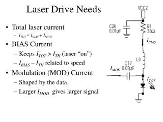
Photocathode Launch System Design • Optical system provides flat-top beam on the cathode • System allows continuous adjustment of the beam radius on the photocathode from 0.6 to 1.5mm. Smaller (than 0.6mm) beam size can be achieved by using smaller aperture after the beam shaper • Design avoids small beam size on optics, which could cause damage
Temporal Shaping • Thales Approach • Narrow bandwidth, long SHG and THG crystals • Using the double pass Dazzler with long crystal for IR beam shaping • UV conversion will decrease the rise and fall time
LLNL Approach • A nonlinear propagation / frequency conversion model has been developed • Frequency conversion simulation includes: • Arbitrary spectral amplitude and phase input (chirped pulses) • Material dispersion, group velocity mismatch and dispersion • Nonlinear Schrodinger equation propagation • Nonlinear harmonic coefficients • Linear and nonlinear absorption • Self-phase modulation • No spatial walkoff in first-generation code (large beam and thin crystals Courtesy of Brent Stuart
A nonlinear propagation/frequency conversion code predicts IR input required for desired UV pulse • Model will be benchmarked against laboratory experiments Optimal Case – UV Converted Pulseshape: 300 IR drive pulse rescaled down by 8X 250 200 Envelope power, MW 150 100 Courtesy of Brent Stuart (LLNL) IR 50 UV 0 -6 -4 -2 0 2 4 6 Time, ps
A nonlinear propagation/frequency conversion code predicts IR input required for desired UV pulse • UV beam • Energy - 3mJ • Efficiency=12%, • Risetime=1.0 ps, • FWHM=10 ps, • Falltime=1.0 ps • Optimal Case – UV Converted Pulseshape: Requires flat-top spatial IR beam • Input IR beam: • Energy - 25 mJ • Supergaussian order - 10 • Spectrum - 8.7 nm FWHM. • SH crystal is 0.225 mm and TH is 0.125 mm. • FWHM gaussian spatial profile - 3.3 mm
Sculpted spectrum 9.4 nm FWHM 8th order supergaussian The input IR pulse has been generated • Pulse is stretched to 10 ps by detuning compressor • 3rd order removed and 4th order added with Dazzler • Dazzler spectral resolution (0.6 nm) allows for ≈8th order supergaussian
Spatial Beam Shaping Newport Refractive Beam Shaper Two aspheric lenses Input Beam Output Beam The beam shaper was tested at the GTF Spatial Profile Flattening of Ultraviolet Laser Pulses with Aspheric Refractive OpticsB.F. Murphy, P.R. Bolton, A. Brachmann, J.F. Schmerge
Spatial Shaping • Spatial Shaping Issues • Feasibility of achieving the shaped beam in harmonic by shaping fundamental • Effect of imaging • Operation under the broad bandwidth • Impact of the non-perfect input beam quality • Internal focus in the shaper is a concern • Tests were done by Yuelin Li at ANL with the Newport shaper – GBS-AR14
Shaping of the IR Beam, Harmonic Generation and Relay Imaging • Shaping of the harmonic beam by shaping fundamental was demonstrated • Imaging is essential for maintaining the spatial shape IR, 30 cm from shaper output, imaged SHG, 30 cm from shaper output, imaged SHG, 30 cm from shaper output, not imaged Courtesy of Yuelin Li (ANL) Center dark spot is due to coating damage
Effect of the Bandwidth • The required spatial shape was achieved at the bandwidth up to 10nm • High quality input beam is important 18nm bandwidth 10nm bandwidth Input Courtesy of Yuelin Li (ANL)
Effect of the Self- Focusing at High Intensity • Internal focus in the shaper causes self focusing at the high intensity and distortion of the beam shape. • To avoid this problem the shaper without internal focus should be used Input power ~ 2.5GW
New Product - High Energy Spatial Shaper • Newport product –GBS-UV H • Does not have internal focus • Constructed of Ultraviolet safe components and processed in Class 5 clean room to minimize outgassing and particulate generation New Shaper Three aspheric lenses
High Energy Spatial Shapers without Internal Focus • Zemax modeling of the transport and launch system was done using the prescription of the Newport High energy shaper • Newport and MolTech loaned the shapers for trials • Tests of the two shapers from Newport and from MolTech are underway at GTF
Testing of the Newport Shaper • Image of the aperture after the shaper Input beam
Summary • Transport system that allows delivery of the beam to the photocathode without distortion of temporal and spatial shape has been developed • Aspheric lenses shaper has been chosen to provide flat top spatial beam shape • Two approaches to temporal shaping are being pursued. • Models has been developed. • Tests are underway • Temporal diagnostics has been developed