Download
1 / 41
410 likes | 420 Views
STANDARD ASCENSION TOWERS GROUP was established on Dec 08 2015 as a domestic business corporation. Larry Jordan II Buffalo,NY. Founded 5 Stems llc a telecommunication infrastructure construction company Minority and vet owned. BS Florida Tech, MBA/PHD Colorado Tech.

E N D
MAE494:Senior DesignProjectReport TheAscensionProject Group#27 NicholasAltanian,JasonD’Souza, AndrewLewis,JoshuaMatter,AlecBrewer May8,2015
LISTOFTABLES Table 1. List of customer requirements………………………………………………………...………………….3 Table 2. Technical specifications………………………………………………………………………….........….4 Table3.Decisionmatrix……………………………………………………………………………………….……8 Table 4. Tower stress analysis results…………………………………………………………………………...14 Table 5. Pulley housing floor stress analysis results………………………………………………………..….16 Table 6. Total cost breakdown………………………………………………………………………..…………..17 Table 7. Tower income………………………………………………………………………………………….....17 Table8.Estimatedsavings………………………………………………………………………………………..18 iii
EXECUTIVESUMMARY This reportconsists of detaileddesigninformationpertaining to the design of a monopole, telecommunications tower, intended to eliminate the need for climbing in order to maintenance communication equipmentlocated on thetower.Thetower design is based on aconventionalelevator, pulley/counterweight, lift system that lowers six individual antenna platforms to ground level for maintenance.The designprocess,embodiment design,designfeasibility analysesand manufacturing/assemblyconsiderations are discussed in detail. iv
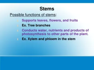
INTRODUCTION • This section consists of a description of our senior design project’s motivating problem.Project goals, deliverables and metrics of project success are also clearly defined.An overview of the contents of this reportis provided in section 1.4. • ProblemOverview • Ourseniordesignprojectisfocusedonthedevelopmentofadesignforanewcellphonetoweraimedto eliminate the issues currently associated with cell phone towers.The primary issue we are concerned with isthedangeroustaskofmaintainingtheequipmentonthesetowers.Towerworkersneedtoclimb towersranginganywherefromafewhundredtoovertwothousandfeetinheight.Witheighteendeaths in2019alone1, tower climbing is considered tobe oneof themost dangerous jobsinAmerica1. • Our project sponsor, Larry Jordan (CEO of SAT Corp), proposed his idea for a tower that would make towermaintenanceentirelyriskfree.Insteadofhavingworkersclimbatower,Mr.Jordanwantsus todesignatowerthatwillbringtheequipmentdowntogroundlevel.Thetowerwillneedtobe capable of allowing maintenance of one carrier without interference of service to any of the other carriers onthetower. • ExpectedProjectDeliverables • Due to the size and complexity of this project, it is important that we define reasonable expectations for final project deliverables. By the end of the project period, we plan to have a fully detailed design that addresses amajorityofthecustomerrequirements.This designwilltakeshapethrough 3D CAD software (Creo Parametric).In order to better convey the function of our design, we plan to animate the 3DmodelthroughCreo.Thegoalistoprovideenoughdetailandinformation,suchthataprototype ofourdesigncaneventually bebuilt for future testing. • MetricsofProjectSuccess • Wehavedecideduponseveralperformancemetricsthatwillallowustoproperlyevaluatethesuccess ofourfinaldesign.Thesemetricsinclude: • How wellcustomer requirements (definedin Section2.1) aremet Estimatedpayback period • Factorsofsafetyof criticalcomponentsbased onfiniteelement and • fatiguelifeanalyses Ouroverallmeasurementofsuccesswillbehowwellourdesignmeetsthecustomerrequirementsdefined inourHouseofQuality.Wewillperformcombinationsofqualitativeandquantitativeassessmentstogauge howwelleachcustomerrequirementwasmet.Thehighestweightedrequirementsarefocusedonthecost and reliability/integrity of our design.The cost of our design will be compared to the cost of a 200 ft. monopoletower(estimatedat$80,000)1.Assessmentofoverallsystemreliability/integritywillrequireFinite Element Analyses (FEA) on major components of our design.Major components of our design will consist of the tower’s structural elements.We will use Creo Simulate to perform our FEA.The goal of our FEA will be to simulate stress responses of major components placed under worst case loading scenarios (includes responses to windforces) and computecorresponding factors of safety. 1.4ReportOverview Thisreportconsistsofadetailedbreakdownoftheproblemathand,conceptgeneration/selectionprocess, andembodimentdesigndetails.Thelayoutofthereportfollowsthestructureddesignprocesswe havebeenfollowingsincewebegantheprojectintheFallsemester.Descriptionsofeachmajorstage intheprocess,alongwiththeirrespectiveoutputs,areprovidedforeachsection. 1http://www.wirelessestimator.com/ 1
PROBLEMCLARIFICATION • Thissectionconsistsofthecustomerrequirementsdefinedforthedesignofourtowerandtheir • corresponding technical specifications. The requirements break down the overall design problem and represent the main driving factors that will dictate the design of our tower.The technical specifications represent quantified design performance targets. • CustomerRequirements • A majority of the customer requirements, listed in Table 1, were developed after our kickoff meeting with ourprojectsponsor,LarryJordan.Theserequirementsconsistofbothinnovativeandstandardfeatures • thatMr.Jordanexpectstoseeinourtowerdesign.AfterreceivingourreviewonourMiniProject2Reports, redundant and unnecessary requirements were removed. Requirements more specific to our proposed design were appended after receiving Mr. Jordan’s review on our embodiment design of “The Octotower”. The customer requirements were weighted according to importance and incorporated into our House of Quality toanalyzerelationshipsbetweenrequirementsandtechnicalspecifications(SeeAppendixA). • Table1.Listofcustomerrequirements 2
2.2TechnicalSpecifications Technicalspecificationswereestablishedbytranslatingthecustomerrequirements,definedinSection2.1, into quantifiable design performance targets. Each technical specification corresponds to a customer requirement and can be measured according to some type of unit.The importance of each technical specification was derived through by establishing the strength of relationships with the weighted customer requirements in our House of Quality (See Appendix A for HOQ). The relative weights/importance from the HOQ, as shown in Table 2, indicate that overall cost and the structural factor of safety are the most importanttechnical specificationsthatwill need to beaddressed in our design. Table2.Technicalspecifications 3
CONCEPTDESIGN • Thissectiondiscussestheprocesswefollowedtoarriveatadesignconceptthatpromisedtosatisfya • majority of the customer requirements defined in Section 2.1.Our process comprised of two different stages.Duringourdivergentdesignstage(discussedinSection3.1),weusedtwodifferentideageneration methods to pool together as many distinct design ideas as we can. We turned to convergent processes (discussed in Section 3.2), to filter our pool of design ideas and finally arrive at a design concept to further pursue. • ConceptGeneration • Our group’s concept generation process consisted of one group generation method and one individual generation method. Our first batch of ideas were generated using the 6-3-5 technique. While we were able togeneratemanyideasthroughthismethod,wequicklyrealizedthattherewasn’talotofvariationamongst • thepoolofideas. • We then decided to try an individual idea generation method in hopes of developing a larger variety of design concepts. We used a forced connection approach through photographs. Each group member postedfivephotostakenfromtheinternetontothegroup’sgoogledrive.Wegaveeachotherafewdays to develop concepts inspired by these photos and the result was a larger pool of ideas with greater variety. Each group member communicated their ideas by sketching and writing short descriptions. In total, we developed a pool of seventeen distinct design ideas. A few examples of the photos we used are shown in Figure1. Figure1. Conceptgeneration photos 5
3.2ConceptSelection Inordertodeterminethebestoverallconceptoutofourpoolofideas,weratedeachidea(onascaleof1- 100)inaccordancetosixofthemostimportanttechnicalspecifications.Weorganizedthisinformation intothe decision matrix, shown in Table3, toarrive atthe concept wewould further pursue. Table3.Decisionmatrix The weighting system used in the decision matrix is designed to apply relative emphasis on the design attributesthataremostimportanttothedesiredoutcome.Theweightschosenreflecttheimportanceofthe specific design attribute. Afterassigningweightstoeachdesign,eachdesignwasscored0-100basedonitsconformitytowardsthat attribute. The Octotower received the highest overall score of 89. This score reflects the overall best coverage of each attribute. The three runner ups are the Bloom “Stacking” System, with a score of 71.2. TheOverlappingPlatformsystem,withascoreof70.7,andtheExteriorLiftingSystem,withascoreof 69.4. The Octotower design beat these designs by a significant amount. However, the runner-up designs stillhavepotentialwithsomeredesign.Theseredesignsprovidealternativesandalsopossibledesignideas thatcanbe used to optimize the Octotowerdesign. 6
4.1.1TowerStructure Thetowerstructureisdesignedtoaheightof190ft. and has a tapered profile (0.574 degree). The taper provides a robust structural design along with sleek aesthetics. The tower’s structural design consists of eightseparatesections. Eachsectionhas a hexagonalcross section (See Figure 4). Sections 2 – 7 have I-beams bolted on at each face of the tower.These I-beams serve as guiderails for the antenna platforms to ride along via guide shoes. There is one antenna platform that rides along each face of the tower (six platforms total).The bottom section houses the drive motors and has a door for easy accessibility when maintenance is needed. The top section of the tower houses the pulleys. Each section is boltedtogether viaexternal flanges. Figure4.Towercross-section Manufacturingconsiderations werekeydriving factors of thetower’sstructuraldesign.Bolted connections were chosen because we wanted to keep the need for welding down to a minimum and wantedadesignthatwouldbeabletousecommon machinery currently used to make monopoles. Transportation and assembly considerations were also crucial to the tower’s structural design.The towerwasdesignedsuch thatthelargest componentofthetoweriscapableoftransportation viatrucks,freightboats, andcargoplanes. External flanges were chosen for joints because they provide a strong structural connection and easyassembly. Figure5.Section4model In ordertoensuresafe structural stability of thetower structure,stress analyseswere conducted at three majorareas of concern(see Section 4.2). Figure6.Drivehousing Figure7.Flangejoint
4.1.2 Antenna Platform and Guide Shoe Each antenna platform is designed to hold ten standard sized (8 ft. x 1 ft. x ½ ft.) antennas and has roughly 36 square feet offloorspaceforadditionalcarrier equipment.The front face of the platform provides120square feetofareaper platform for advertising space (see Figure 8). The framing of the platform consists of 2 in.roundtubesconnectedtograteflooring. Thesetubesareconnected,viaU-bolts,to 1¼in.tubesthattheantennasmountonto viamountingbrackets. Figure8.Fullplatformmodel Each platform has two custom designed guide shoes that ride along the I-beams bolted along each face of the tower.The guide shoes keep the platform in place such that it is only capable of moving vertically. Each shoe consists of eight purchased wheels with load ratings well above the estimated platform weight. Incorporated into the guide shoes are two eyebolts that connect to the steel cables used to lift/support the platform.TheguideshoesareconnectedtotheantennaplatformviasteelI-beamsandboltedconnection. Figure9.Guide shoeassembly/sectionview Designforenvironmentconcernsweretakenintoaccountwhendesigningtheantennaplatform.Acommon problem with communication towers is that they often serve as nesting spots for birds. Often times, if there is a nest on a tower, tower workers are either prohibited from working on the tower and/or have to contact local wildlife agencies for further instruction on how to handle the situation.This can severely impede necessarytowermaintenance.Asimple,cheapandeffectivesolutiontothisissuewouldbetoplacenetting along the backside of theplatform and birdspikes onthe top ofthe platform in order toavoidnesting.
4.1.3Drive/LiftSystem Thedrive/liftsystemissimilartothatofthe conventional elevator.Six gearless traction motors, located at the base of the tower, release and retract steel cables, connected to the counterweight, in order to lower and raise the platform, respectively.There is onemotorforeachplatform/counterweight, thus allowing foreachplatform toberaised/lowered independently from one another. Maintenance for one carrier does not interfere with the service of the other carriers located on the tower. In order to significantly reduce costs, an existing gearless motor that meets necessary specifications was chosen. These gearless motors can be operated remotely via a control box locatedoutside ofthetower. Figure10.XINDAWWTY gearlesstractionmotor The counterweight is designed to be roughly 75% of the load placed on the antenna.The weight of thecounterweightcan beeasilyadjusted to account for varying loads placed on the platform. With the counterweight counteracting the load of theplatform,themotorsatthebaseoftheplatform are only responsible for providing enough power toliftthedifferenceinweightbetweentheplatform and counterweight, thus significantly reducing the required motor size. Tension is kept in the cables between the motor and counterweight in order to keepthecounterweightinplaceasittravelsalong the tower. Counterweight frame and weights that meettheweight andgeometricaldesign requirements are readily available for purchase from numerous elevator supply companies. Figure 11. Hollister Whitney counterweightframe Two pulleysper platform,locatedat thetopof thetower(see Figure12),changethedirectionof thesteel cables that attach the antennaplatform to the counterweight.Boththe pulleys and steel cables are purchased components that meet theload requirements with a factorofsafety of 3. Figure12.Pulleyhousingconfigurationand model
4.1.4Brake/Fail-safe The primary brake is integrated into each of the six gearless traction motors.This brake will hold the antenna platform in placeduring regularoperation. In the unlikely event that the cables snap/fail, elevator buffers, designed to bring free falling elevators to a safe stop, are located at the bottom of the tower.These buffers are bolted into the ground directly underneatheachantenna platform.Purchasedhydraulicbuffers, thatmeetimpactload/speed requirements, were chosen for our design. The buffers require little to no maintenance and can be easily replaced if needed. • Figure13. Oleo SEB18 Hydraulic Buffer • DetailedDesignAnalysis • Duetothefactthatamajorityofthetower’sdesigniscomprisedofpurchasedcomponentswithknown • load ratings, design analyses was only performed on several components of major concern. These components include the overall tower structure, the I-beam guiderails, and the top section (pulley housing) ofthetower. • TowerStressAnalysis • Finite Element Analysis (FEA) was used to determine the wall thickness of the tower that would achieve a target factorof safety of 1.5.The design wastestedunderworst-case-scenario loadingconditions. • Known: • Materialpropertiesofthetowerstructure(ASTMA572–65),towergeometry,airpropertiesatSTP, and platform/counterweight loads are known. • Assumptions: • Thefollowingassumptionsweremadetosimplifyanalysisofthetowermodelwhilestillmaintaining validityofresults: • 110mphwind • Angleofattackisat0degrees • Joints atthe flange are rigidconnections • Baseof tower is rigidly constrained • Weightfromantennaplatformsandcounterweightsactverticallydownwardfromthetopof thetower • Towerdragcoefficientis0.95
Free Body Diagram and Relevant Equations: Figure14representsasimplefreebodydiagram showingthe locationofthewindand platform/counterweightloadsonthetower.Eq. • was used to determine the force from the windacting on thetower. • WindForce(FD): FD=1ρv2CdA Eq.(1) 2 ρ=airdensity v=windspeed Cd=dragcoefficient A=effectivearea • Figure14.Towerfreebodydiagram • Results: • Aftersimulatingthestressinthetowerwithfivedifferentwallthicknesses,theoptimalwallthickness • was found to be 3/8”.This thickness resulted in a maximum stress of roughly 41,000 psi and a corresponding factorofsafetyofroughly1.56.Table4shows thesimulation resultsand correspondingfactors of safety. Table4.Tower stressanalysisresults Note:Von-Mises, displacementand convergencediagramscanbefoundin AppendixF
I-BeamStressAnalysis • TheI-beamGuideRailisthecomponentinwhichtheantennatravelson.Theoperationofthetowerstrongly dependsonthereliabilityofthiscomponent,soitisnecessarytoperformastressanalysisthatwillconfirm • thereliability.Theantennaissupportedintheverticaldirectionbyacablethatisconnectedtothetopguide show. At any given position, the mass of the antenna creates a moment about the top guide shoe, which is resolved into normal forces applied to the outer face of the I-beam at each of the lower guide shoes. Additionally, any wind exerts a force on the antenna, which results in a moment on I-beam at each guide shoe. • Known: • The platform geometry, I-beam material (ASTMA36),I-beamsize (W14x90),andairproperties at STPare known. • Assumptions: • 110mphwindload • Angleofattackis0degrees • I-beamis rigidlyconnectedtothetowerface • Free-BodyDiagram/Equations: • Figures15representstwosimplefreebodydiagramsshowingthewindforcesandload/moment • fromtheantennaplatformactingontheI-beam.Thewindforceactingontheantennaplatform was calculatedusing Eq.(1) and the antenna platformmomentwascalculatedusing Eq.(2). • AntennaPlatformMoment: M=Fgd Eq.(2) Fg=forceofgravityofplatform d = distance from Ibeam to platform'scenterofgravity • Figure15.I-Beamfreebodydiagram • Results: • TheresultsfromtheFEAstressanalysisshow amaximumstressof384psi.Incomparisontothe • steelI-beam’syieldstrengthof29,000psi,thisresultsinafactorofsafetyofroughly76andis therefore structurally sound. Note:Von-Mises, displacementand convergencediagramscanbefoundin AppendixF
PulleyHousingStressAnalysis • Thefloorofthepulleyhousingexperiencesagreatdealofforcesincetheweightfromallsixantenna • platforms and counterweights are acting on the pulleys bolted onto it.FEA, through Creo Simulate, was used to determine if the housing design was structurally feasible and, if so, the optimal floor thickness that wouldprovide a factor of safety of 6. • Known: • Thefloorgeometry,pulleyhousingmaterial(ASTMA572–65)andplatform/counterweightloads are known informationnecessary for analysis ofthe pulley housing floor. • Assumptions: • Forces fromwind loadsare negligible • Platform/Counterweightloadisperfectlyvertical • Pulley housing flooris rigidly constrained at thebolted flanges • Free-BodyDiagram: • Figures16representsafreebodydiagramshowingtheforcelocationsfromeachofthesix counterweight/pulley systems.TheX represents a vertically downward force. • Figure16. Pulleyhousing floorfree bodydiagram • Results: • Aftersimulatingthestressinthehousingfloorwithfivedifferentfloorthicknesses,theoptimal • thickness was found to be 9/16”.Table 4 shows the simulation results and corresponding factors of safety.This thickness resulted in a maximum stress of roughly 7,700 psi and a corresponding factor of safety of roughly 8.5.Table 5 shows the simulation results for each thickness and correspondingfactors of safety. Table5.Pulleyhousingfloorstressanalysisresults Note:Von-Mises, displacementand convergencediagramscanbefoundin AppendixF
ProductionandCostAnalysis • Thissectiondiscussesintendedmanufacturingandassemblyproceduresforourdesignalongwithacost analysesthatprovides anestimated payback periodonthe tower’s initialinvestment. • CostAnalysis • Adetailedcostanalyseswasconductedtodeterminethepaybackperiodoftheinitialinvestmentforour towerdesign.Thecostestimationofthedesignwasbrokendownintomaterial,manufacturing/assembly, • servicing, andinsurance costs.The following assumptionswere made for cost estimations: • Thecostforthefabricatedsteelsectionswereestimatedatarateof600$/metrictonofASTM A572–65 high strength low alloysteel • The insurancecost forcoverageon the towerandlocationsite isestimatedto be$250,000. • Therentalratesforthetrailerandcranewerereceivedfromaroughpricequotefromalocalheavy equipmentsupplier. • Theoperatingratesforthemanufacturingprocessisestimatedafterconsultingseveralworkers • employedintheindustry. • Thepricesforallpurchased(offtheshelf)partsarebasedonquotationsreceiveddirectlyfrom suppliers. • Theoverallsavingsontheprojectwascalculatedbasedondataobtainedfrom wirelessestimator.com(as suggested byproject sponsor). • Table6showsabreakdownofthetotalcostforthetowerdesign.Adetailedbreakdown,alongwithalist ofall parts/materials, canbe found in Appendix D. Table6.Totalcostbreakdown The payback period of the tower’s initial investment is an important metric of costing and overall design success.It is defined as the length of time required to recover the initial investment.The payback period wascalculatedusingEq. (3) andTable 7 whichlistsestimated sourcesof income fromthe towerdesign. Total Investment Total IncomeperYear Eq.(3) PaybackPeriod= Table7.Towerincome PaybackPeriod=2yearsand3months Inadditiontothepaybackperiodoftheinitialinvestment,animportantcostmetricforthedesignishowit standsagainst existing monopoles of similarsize.Table 8 shows estimated costsavingsper year.
Cost EstimatedSavings($) GeneralLiabilitiesCoverage $1,000,000 UmbrellaCoverage $2,000,000 StatutoryWorkersCompensation $28,288 CoverageforPropertyofOthers $4,000 OSHA Fines from Fatalities and Injuries $125,000 Total Estimated Savings $3,157,288 Table8. EstimatedSavings 4.3.2ManufacturingDetails This section discusses intended manufacturing operations for custom components of the tower’s design which includes the towerstructure, guide shoe, pulleyhousing, counterweightandtheantennapla TowerStructureManufacturing The towersectionsare thinwalledmembersandwillthereforebemanufacturedfromsheetsofsteel.The sheet will be cut into a slight trapezoid shape to allow for the taper of the cross-section of the tower. The trapezoid will be cut to length (height of the desired section), with the top and bottom sides supplying the perimeter length of the tower section along with a3 inchoverlap for the weld to close the section. Thechannelswheretheguiderailwilllaterbeattachedwillthenbepressedintothesheetintheirrespective locations. The sheet will then enter a metal break to be bent to 60 degrees, thus creating the hexagonal crosssectionofthestructure.Theremainingoverlapwillthenbestickweldedtoclosethetowersection toinsureastrong bond. The external flanges begin as steel extruded to a 1” X 8” cross section. This stock will be cut to a length matchingtheperimeterlengthbetweentheguideslotsonthetowersectionitistobematedwith.Thework piece is then bent 90 degrees lengthwise along its center, then 60 degrees at the midpoint of its length, matching the corner of the section.Holes are then drilled into the outer flange surface to allow them to be boltedtogether during assembly. GuideShoeManufacturing Theguideshoewillbeacastproduct.Steelwillbepouredintoaplastermolddesignedtospecified dimensions.Theresultingfinishofplastercastingisrelativelysmoothandwilllikelynotrequiremachining. This will,however,be confirmedto insurethe proper alignment ofthe wheels thatare to be laterattached. Oncethecastingisfinished,holedwillbedrilledtoallowthewheelassemblytobeboltedtotheguideshoe in their respective locations. The wheels and bearings are purchased parts that are fixed to the guide shoe viashort bolted axles. PulleyHousingManufacturing Thefloorofthepulleyhousingismadeupofasteelplatethatisdiepressedtothespecifiedgeometryso the pulley assemblies can be mounted to their respective locations. The remaining portion of the pulley housing (same manufacturing procedure as the tower structure) is welded onto the steel plate floor.The purchased pulleys are bolted ontothefloor. tform.
AntennaPlatformManufacturing • The curved steel tubesof theantennaplatformbeginasstandardsteelpipe andare benttothe specified • radius.Flanges are welded onto theend of eachcurvedtube.The antennamountingpipes are simply standard steelpipes cuttospecifiedlength.Thetubesareconnectedtogether via bracketsand U-bolts. Thetwo platform arms are madeof I-beams with two plates weldedon at each end.Holes for thebolted connection are drilled into each plate as one side is attached to the flanges of the rounded tubes and the otherside isattached totheguideshoe. • AssemblyDetails • The following stepsoutline thetower’sgeneral assembly process: • The concrete tower foundation is poured to the depthandsizespecified bythesizeofthetower to beinstalled.The baseconsists ofconcrete and rebarstructure togive strengthand support • tothe concrete pad.Conduits are utilized tobring thepower andsignal carryingwires to the center of the tower from theexternal control box. • The drive housing sectionof the tower is bolted to the concretebase and therequiredelectrical lines areinstalled.The gearlessmotors are bolted tothe base of the tower in theirrespective locations andnecessary electricalconnections are made. • The buffersareboltedinto thegrounddirectlyunderneathwheretheantennaplatforms would land. • A crane is usedto lift theremaining sectionsatop thelowersections.The sections arebolted together on their flanges.After section 2 is boltedin,a crane willfix each antenna platform into placeon theguiderail. • When thetop sectionis installeditis propped up on spacers allowingthe requiredclearance to spool the lifting cables down the interior of the tower to the winding drums. A temporary scaffolding ismountednearthetopof thetower to allow technicians to guidethe cablesand attach the counterweight. The cables are lifted to the top of the tower using the crane and the counterweights are attached to the cablestotheir properpositionsasthe cablespass over the pulleys.Thelower part of the cable is attached tothe windingdrum and wound about the drum toinsure good connection before theweight oftheantenna platform ison the cable.Whenthe cables aresecured the spacersareremoved and thetop section isboltedto the tower.
5 CONCLUSIONS,RECOMMENDATIONS &FUTUREWORK Afterconductingmultiplestressanalysesoncriticalcomponentsandanoveralldetailedcostanalysis, results point towards the conclusion that the design is feasible and development efforts should be further pursued. The tower’s design was capable of bringing together numerous existing parts, mainly associated with the common pulley/counterweight elevator system, to create a system that will eliminate the risk of death or injury while servicing telecommunication towers.This added safety feature significantly reduces highinsurancecostscurrentlyassociatewithcommunicationtowers.Withampleadvertisementandcarrier leasingspaceavailable,thetower’sdesigniscapableofgeneratinglargeamountsofincome,thusmaking upfor the higher initial investment costs. Referring back to the customer requirements (listed in Table 1), the tower’s design meets most specified requirements. Major requirements, including ‘safe to service’, ‘capable of supporting at least five carriers, and ‘isolated carrier maintenance’, have all been met.Certain requirements, including ‘remote antenna control’ and ‘deliver power to communication equipment’, still require further designing, but incorporation into the current design should not be an issue.In addition, another failsafe incorporated into the design would be highly recommended. One potential location for an additional failsafe would be a friction brake locatedintheplatform’s guide shoe. The next step to take with this design is to conduct further testing via prototyping.It would be best to build a full scale model of the tower and have it exposed to harsh environments that these towers will need to endure.Since this tower is heavily influenced by the conventional elevator, it is recommended that professional elevatorengineers arehired tooverseetheprototypestageof design.Civil/structural engineers should also be hired to ensure that proper foundation and overall structural requirements are met.Further development of the design will result in a well optimizedtower that would surely be an attractive alternative to the conventionalmonopole currently in the telecommunication industry.
REFERENCES • 1)Elevators (ThirdEdition). ByF.A. Annett,McGraw-HillBookCompany • - Provided us with majorityof the inspiration onourtower’s liftsystemdesign • 2)LarryJordan(CEOofSATCorp.) • - Provided uswith designfeedback andhelpedestablish majorityof ourcustomer requirements • 3)HollisterWhitney • Provideduswithinformation/specs oncounterweight/frame • http://www.hollisterwhitney.com/ • 4)McMasterCarr • - Provided us with information/specs onpulleys, cable,wheels and bolts • 5)Oleo • Provided us with information/specs onelevator buffers • http://www.oleoinc.com/products/elevator • 6)WirelessEstimator • http://www.wirelessestimator.com/breaking_news.cfm • Provideduswith majorityof theinformation oncommunication towers • 7) XINDA • Provided us withinformation/specs on gearlessmotor • http://www.xindasz.cn/
B.4–CollapsibleArmSystem Description: This system consists of several levels of mechanical arms that surround the tower. Each arm belongs to a specific broadcaster and provides 360 degrees of signal. When it is necessary to loweraspecificbroadcastingarm,thearmfoldsinseveraldifferentcalculatedlocationstocollapse the arm to a size that can fit inside of the other arms without any interference. Each level will ride onitsownspecifictrackthatwillcarryitupanddownthetowerwhenthearmiscollapsed. Sketch: B.5–SuspendedTierDesign Description: This design is a seriesof tiers supportedfrom above by several rigid vertical arms, all connected to a structure at the top of the tower. The tiers are located at different levels and they get progressively smaller going down the levels. This allows for each tier to fit around all of the tiers below it, and the individual levels allow for full 360 degree coverage. When an individual tier needs to come down for maintenance, a transporting device travels tothe selected tier and supportsthetierfrombelow.Theuppersupportsdisengageandthetierisallowedtotravel down the tower. The size of the tiers can either increase or decrease going down the tower, depending onthebenefitsofeachscenario. Sketch:
–RotatingAntennaTier • Rotating Antenna Tier Description: • This design incorporatesseveral tiers or levels of rotating antennas.There are 9antennas on each tier that broadcast a range of40 degrees apiece. The tiers,however, are divided into 10 • sections: 9antennasand1 open section. Thisopensectionprovidesthe spacefor individual antennastomoveupanddownthetower. When maintenance isneeded on aspecifictier, the • tier willrotateand,oneby one,aligneach antenna with thetransporting track,where it can travel • downthetowertobeserviced. • Sketch:
B.8 –Foldable/ExpansionSystem Description: The towerhere is hexagonalshaped.Each tier isdesignedin sucha way that it can completely expandfromitstriangularshapetoacompletelyhorizontalbeamandbebroughtdownfroma side ofthe tower. There is a travelerforeach tier onaside ofthetower. Thereareelectromechaniclocksandhydraulicsinvolvedtoensureproperexpansion/foldingof the mechanism tobring itupanddownthetowersafely. The mainholdingarm which is housed on the traveleris ahydraulicenforcedtelescoping armthat can expandandretract. It is designed such to ensure the tier being broughtdowndoes not interfere withthe other tiers. The travelingmechanismhereisabunchofrollershousedinabracket. Thesystemis hydraulic in nature and this is what drives the rollers. The mechanism is controlled from the bottom of the towerby an operator/technician. This provides greatdeal of accessibilityconsideringeachindividual tiercanbe broughtdown without interrupting operation of the others. Maintenance runs will be very quick if all the steps are properly followed bythe operator/technician. Sketch:
B.9–ExteriorLiftingSystem Description: The individualantennascanbesent up the travelingsystem likeonaconveyorbelt. The travellingsystemisonboth sidesofthemaincentralmonopolestructure.Theantennascan be sent upandbroughtdown from eithersidebasedontheirpositionon the structure. The travelling system is onthe main central monopole structureandalsooneach ofthe individual tiers housedon the monopole. The arm aboutwhich each antenna ismounted has degrees offreedom inthe sphericalcoordinatesystemandcanbe remotelycontrolledfrom the ground by the operator/technician to align the antennais the desiredorientation. The limitationsto thisdesignare that the antennaswouldhave tobewirelessandalsobe powered by solarorawireless medium. Anotherlimitation is that, in somecases, multiple antennasonthesametier wouldhavetobebroughtdownduringasinglemaintenancerun, even ifthe run is scheduledonly for one specific antenna. Sketch: B.10–ConcentricRings Description: The use of concentric rings that attach to the tower at two points along a track system. The track system raises and lowers the rings. The workings of the track system will most likely be a simple chain-pulley system powered by anelectric motor at thebottom. The ringswouldbelowered independently, theantennasserviced,repositionedand thensentbackup. Sketch:
B.11–RotatingCollars Description: There will be a track system to send the brackets that hold the antennas up and down. There is rotating collars at predetermined heights along the tower. The bracket to hold the antennas will beconnectedtothetowerbytwopointsofcontactforstability. Sketch: B.12–SpiralTrack Description: There will be a track that wraps around the tower letting the brackets that hold the antenna to get uptothe collars that allow themtosettheir azimuths. Sketch:
B.13–OverlappingPlatforms Description: There are fourtracks onthetower. Therearefourplatformsthat canholdoneantennaeach. The loopsareall differing diameters, letting the antennas belowered andserviced independently. Sketch: B.14–Antenna Retriever Description: There is an inner antenna retriever that sends the antenna up to a set cut out portion of the tower and it popsthrough the tower. The antenna would not beable to change azimuths. Sketch:
B.15–MultipleTowers Description: Thereis a circulararray of “towers” (bars)that each house a trackand can hold oneantenna. The circular arrayof bars willneed to have a circular ring on theinside to supportthebars ina verticalorientation. Sketch: B.16–TheWillowTree Description: This designincorporateslongcablessupportingeach tierofantennaeatits respectiveheight. Thetiers are circularandeach of differentradiusallowing themtopass by each otherso they can beloweredindependently.The topand bottom ofthetower wouldhave fixed guides for the cables and pulleys to direct them back to the center of the tower.At the base of the tower some sort of transmissioncoulddeliver thepower to mobilizethe tiers.Coarseazimuth adjustment wouldbe carried out on the ground but finetuningwouldberemote controlledmotors at each antennae. Sketch:
B.17–CircularTiers Description: The towers would have a fixed c-shaped frame at the predetermined heights were the antennae’s are desired.The gap in each tierwould align with the othergapsandmounted on thetower in that gap would be the lifting mechanismfor the antennaeframesegments.The antennae would be mounted tothe segments onthegroundand then elevated totheir respective tier.Another mechanismat eachtierwouldrotate thesegment onto thefixed frame. Again coarse azimuth adjustment would be carried out on the ground but fine tuning would be remotecontrolled motorsateach antennae. Sketch: B.18–FixedCollapsibleFrameSegments Description: Eachtier would again have permanentsupportsaround the portion ofthe tower that does not contain the elevating mechanism.The structures that hold the antennae’s will be three sided figuresthat are collapsible into triangles.Whenthestructures are“folded” they canthenbe translated aroundthe towerto theelevatingmechanism.The designof thefixedframingofeach tier allows the folded structure to pass without disturbing the lower towers. Corse azimuth adjustmentwouldbe carriedoutonthegroundbutfinetuning would be remote controlledmotors ateach antennae. Sketch:
APPENDIXC–SupplierSpecificationSheets C.1–GuideShoe Wheel(Supplier:McMasterCarr) C.2– GuideShoe WheelAxle(Supplier:McMaster Carr)
APPENDIXD– DetailedCost Breakdown(Billof Materials) • MaterialCosts • TowerStructure • *The towersectionslisted below are fabricatedusing ASTM‐A572‐65,HighStrengthLowAlloy • Steel. D.1.2Bolts *Thebelow listed bolts areallASTMA307gradeAHexbolts.
D.1.3AntennaPlatformAssembly D.1.4–Drive/LiftSystem
D.2– Manufacturing/AssemblyCosts D.3–TowerServicingCosts D.4–InsuranceCosts APPENDIXE–DesignDrawings PDFfilesof design drawings have beenattachedtothis report
APPENDIXF–AnalysisResults F.1 – Tower Analysis VonMisesFringePlot DisplacementFringePlot
F.2–I-BeamAnalysis VonMisesFringePlot DisplacementFringePlot
F.3–PullHousingFloor Analysis VonMisesFringePlot DisplacementFringePlot