Download
1 / 69
690 likes | 731 Views
STANDARD ASCENSION TOWERS GROUP was established on Dec 08 2015 as a domestic business corporation. Larry Jordan II Buffalo,NY. Founded 5 Stems llc a telecommunication infrastructure construction company Minority and vet owned. BS Florida Tech, MBA/PHD Colorado Tech.

E N D
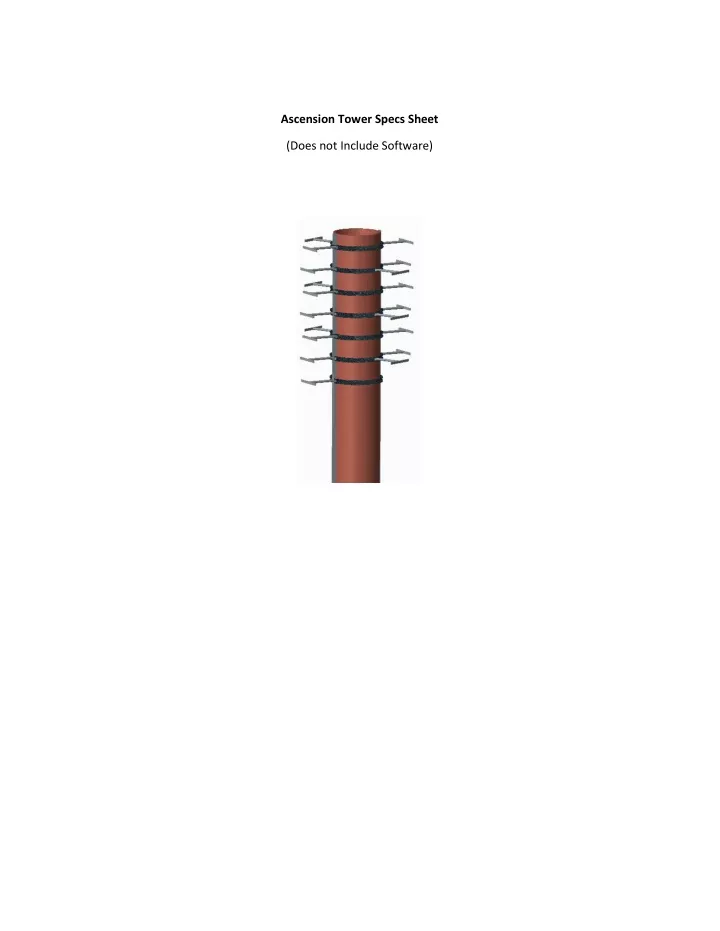
Ascension Tower Specs Sheet (Does not Include Software)
TABLE OF CONTENTS Title ................................................................................................................... Error! Bookmark not defined. TABLE OF CONTENTS ................................................................................................................................ i LIST OF FIGURES ...................................................................................................................................... iii LIST OF TABLES ........................................................................................................................................ iv EXECUTIVE SUMMARY .............................................................................................................................. v 1 INTRODUCTION ........................................................................................................................................ 1 Background .......................................................................................... Error! Bookmark not defined. Problem Definition .........................................................................................................................1 Expected Deliverables ....................................................................................................................2 Conclusion ........................................................................................... Error! Bookmark not defined. 2 PROBLEM CLARIFICATION .................................................................................................................... 2 2.1 Customer Requirements ...........................................................................................................2 2.2 Technical Specifications ............................................................................................................4 3 CONCEPT DESIGN ................................................................................................................................... 5 3.1 Concept Generation ..................................................................................................................5 3.2 Concept Selection .....................................................................................................................6 4 DESIGN & ANALYSIS ............................................................................................................................... 7 4.1 Embodiment Design ..................................................................................................................7 4.2 Detailed Design Analysis ...........................................................................................................9 4.3 Production and Cost Analysis .................................................................................................. 11 Assembly ..................................................................................................................................... 13 Cost Analysis ................................................................................................................................ 15 4.4 Prototype and Testing ............................................................................................................. 18 5 CONCLUSIONS, RECOMMENDATIONS & FUTURE WORK ............................................................... 19 APPENDIX A .............................................................................................................................................. 22 Customer Groups ......................................................................................................................... 22 Engineering Specifications ............................................................................................................ 26 House of Quality .......................................................................................................................... 27 APPENDIX B .............................................................................................................................................. 30 Choosing the Best Design ............................................................................................................. 30 APPENDIX C .............................................................................................................................................. 35 Advanced Screening Process ......................................................................................................... 35 APPENDIX D .............................................................................................................................................. 38 Rating Decision Matrix ................................................................................................................. 38 APPENDIX E .............................................................................................................................................. 43 Boom Analysis .............................................................................................................................. 43 APPENDIX F ............................................................................................................................................... 45 Motor Analysis ............................................................................................................................. 45 i
APPENDIX G .............................................................................................................................................. 46 Heat Calculations ......................................................................................................................... 46 APPENDIX H .............................................................................................................................................. 47 Winch Calculations ....................................................................................................................... 47 APPENDIX I ................................................................................................................................................ 48 Part Drawings .............................................................................................................................. 48 Process Plans For each manufactured component ......................................................................... 58 ii
LIST OF FIGURES Figure 1: Full Tower Figure 2: Antenna in the Elevator Shaft Figure 3: The Elevator Shaft lining up with an antenna and the Horizontal Track Error! Reference source not found. Figure 7: System Reliability Figure 4: Boom Loading Figure 5: Roll Calculations Figure 6: Winch Free Body Diagram Figure 8: Roll with no Slip Figure 9:Lifting Force vs. Weight of Antenna iii
LIST OF TABLES Table 1: List of Customer Requirements with brief explanation Table 2: Engineering Specifications with Explanations Error! Reference source not found. Table 4: Matrix of all possible design ideas Table 5:Example of Weighted, Normalized Decision Matrix Table 6: Isometric Views of all Manufactured Parts Table 7: Time Needed for Raising/Lowering Antenna Once Table 8: Approximate Assembly Time for each level of the Cell tower Table 9: Major Structural Component Costs Table 10: Tower Mechanism Costs Table 31: Cost of Retrofit Table 4: Bill of Materials iv
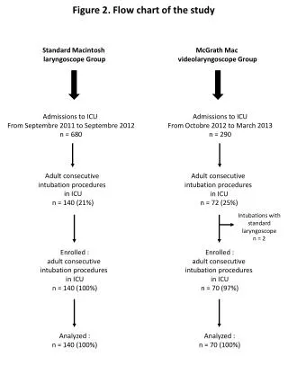
EXECUTIVE SUMMARY This project focuses on a problem stemming from the growing cellular network in the United States, indicated by the increasing number of cell phone users in the 21st century. This project focuses on the design of the monopole cell phone tower. The design of the monopole has created an unsafe work environment for laborers performing maintenance on the antennas, as they are installed hundreds feet in the air. Technician’s deaths relating to on the job falls are drastically increasing; there were 13 reported climbing-related deaths in 2019– more than the two previous years combined. With consideration of the 250,000+ cell towers already erected across the United States to service the 327 million mobile phones currently in use, this project presents a redesign for both entirely new towers and provides a guide to retrofitting existing monopoles. The goal of this redesign is to completely eradicate the need for climbing in maintenance work without compromising overall signal capabilities. The design constraints were laid out and defined by CEO, Larry Jordan , the sponsoring organization of this project. To eliminate the need for climbing, a new monopole design is to be devised such that the antennas can come to the ground. With this, the project sponsor also emphasized the need for targeted maintenance of antennas. In addition, the new tower must be equipped to service seven different carriers – meaning seven different tiers of antennas. The antenna raising and lowering system must also be cognizant of carrier interference. As an antenna from one specific carrier scales up and down the monopole, it must be able to come down without disturbing the signal of other carriers – adding another layer to the targeted maintenance requirement. Through a conceptual design phase techniques such as the 3-5-3 and screening matrices were utilized in order to generate and subsequently eliminate potential design options. Within the project group, the final design of a twelve-sided monopole was selected. This design integrates a winch-pulley system for vertical antenna movement up and down the monopole, and motors for rotational antenna movement about the monopole. The main goal of the redesign was to create a safer working environment for technicians, after this major concern the next largest design driver was cost. A concerned effort was made to minimize cost while increasing efficiency of antenna maintenance and installation. Through a preliminary cost analysis in which many different costs were considered (including labor, maintenance, insurance, and part costs) the overall redesign of the monopole was deemed economically feasible. The subsequent sections of this report include qualitative analysis through a complete conceptual generation, as well as quantitative analysis through detailed design calculations (structural calculations, heat transfer calculations, etc.), cost analysis, system reliability, and working assembly calculations. v
1 INTRODUCTION In a cellular network, cell phone towers are fixed-location structures with electronic communications equipment that distribute and receive wireless signals to and from mobile devices over a given geographical area. From a Telecom Regulatory data evaluation in November 2019, there are 327 million mobile phones currently in use in the United States, exceeding the national population of 317 million1. The last decade has seen an exponential growth in the size and complexity of the mobile network; according to the digital analytics company comScore, the number of U.S. smartphone subscribers has shot up by a factor of 44, from 3.5 million in 2005 to 198 million in 2020. To provide coverage for such a high volume of cellular devices and compensate for the growing mobile network, over 250,000 cell phone towers have been erected across the United States1. The masts of the cell phone towers are generally several hundred feet tall to ensure maximal transceiver range for the antennas and radio frequency (RF) devices. The height of these masts is also predicated by the need to service multiple wireless communication providers, each of which have distinct data networks – many cell sites in the US serve the four main carriers (AT&T, Verizon, Sprint, T-Mobile), and some also service international and/or regional companies. For the most part, the cell carriers do not own their own towers; they instead pay tower companies to lease a space for their antennas. The three major companies Crown Castle, SBA and American Tower own 90% of the 250,000 towers nationwide. There are also general contractors such as MasTec and Ericsson that provide maintenance and upgrades on the towers. Overall, the main cell phone carriers who provide the services do not have a stake in the day-to-day activities at the site, as long as their antennas are solely providing service and are not invested in any other operation. Due to this lack of responsibility, the upkeep of the towers has not been a priority. As a result, the towers have become very unsafe to work on – this is evidenced by the 18 deaths in this industry last year2. With the rising number of deaths each year at the cell sites, efforts must be put forth to create a working environment that caters to both worker safety and economic feasibility. Problem Definition According to the Occupation Safety and Health Administration of the U.S. Labor Department, 13 workers died at communication tower worksites in 2019 in climbing-related accidents – more than in the previous two years combined. With an exponentially increasing death toll, efforts must be pursued to protect the workforce while also enticing companies to invest in new technology3. Eliminating the need for climbing cell phone towers is the most important factor in providing a safer workplace for the contractors in this field. A new monopole design will be needed to meet this requirement, as the current design statically places the RF devices hundreds of feet up the cell phone tower. The selling point of this technology for companies is its rate of return; the unavoidable increase in parts and cost would be offset with a faster maintenance time and subsequently lower labor and insurance costs, as workers would now be able to work on the RF equipment from the ground. A cost analysis would validate this design for its feasibility in industry. Eliminating climbing in maintenance work for cell phone towers allows for much safer work conditions and opens a new door through which profitability can be maximized. 1"16th Mobile Competition Report." Home. N.p., n.d. Web. 5 Nov. 2019. 2"Top 10 Most Fatal Occupations - Listverse." Listverse. N.p., n.d. Web. 22 Nov. 2019. 3 "Construction Industry | Communication Towers." Construction Industry | Communication Towers. N.p., n.d. Web. 15 Nov. 2019. 1
Expected Deliverables Complete set of technical drawings o A working CAD model (individual component and assembly drawings) o Short simulation videos of the mechanisms in action (including simulations of the antennas moving around the tower as well as their vertical movement). Full analysis on the redesigned components of the tower o Focus will be given to redesigned components o Using CAD model an FEA will be performed Design for X consideration will be addressed o Cost analysis (a rough goal is to keep the cost of the redesigned tower to roughly 30% higher than current monopoles, this is a figure given by Mr. Jordan) o Reliability analysis o Manufacturability analysis (including a manufacturing plan and a set of process plans for each new component) o Design for assembly A representative horizontal track prototype will be provided to show how the system will work o The prototype and simulation video will work in tandem to show how our system works. The remainder of this report is broken down as follows. Section 2 details why a cell phone tower redesign is beneficial, and puts forth the design factors that must be considered before such a task can be accomplished. From there Section 3 goes on to discuss the specific design process that we followed as a group to come up with our preliminary design. Section 4 then describes our embodiment design phase – this section will include an explanation of the physical system and its workings. The next section focuses on detail design through and an analysis of the motor, boom, wheels, and winch. Finally, we discuss sections such as manufacturing processes, material selection, design for assembly, reliability, and cost analysis. 2 PROBLEM CLARIFICATION This section contains information that pertains to the design factors and how they impact the customer requirements and ultimately dictate the design process. It also includes a list of consumer requirements and engineering specifications (APPENDIX A contains the complete list for both with explanations). The last portion of this section contains a list of all mechanical components and how they meet the required technical specifications. 2.1 Customer Requirements Design Factors: Below we will list a few of the design factors that helped drive our design Technological Factors: Antennas must come to the ground Maintenance on one antenna must not interfere with signal from a different provider 2
Economic: Total cost of cell tower must remain low The new system will allow carrier providers to hire non-climbing technicians which will lower total maintenance costs Keeping moving parts on the ground will reduce repair costs to the system Government: Must comply with OSHA regulations4 Customer Requirements Below in Table 1 is a list of the customer requirements that are added to our system from a conventional tower due to the movement of the antennas. It is not a comprehensive list of customer requirements for a cell phone tower; for a complete list reference APPENDIX A. Explanation Customer Requirement Workers no longer have to climb Area of Concern Economic, Social, Government Technological, Global, Economic, Government Worker safety is the main motivation for this project, and a big part of keeping the workers safe is eliminating the climbing of the cell phone towers. If all the work can be done at ground level, maintenance time will be reduced drastically. This would also make it possible for the cell phone companies to have their own technicians work on the antennas rather than hiring specialized workers. Easy to work on Other carriers stay in service when work is being done Technological Factors, Economic Lowering one carrier at a time is a necessity. The only carrier that can be affected by the work going on in the tower is the provider receiving maintenance. Technological, Global, Economic, Social, Government Technological, Economic A system where the workers are brought up to the antennas using a raised platform is feasible, but is not as good as lowering the antennas. Any time workers are at a great height there is the potential for serious injury and death. If the antennas come to the ground, the workers are no longer placed in danger. Cell phone tower must be able to hold the necessary equipment for more than one cell phone carrier. The position of the antennas affects the coverage provided by that carrier so the antennas must be able to be adjusted. Wires will make it very difficult for the antennas to be lowered. A wireless option to transmit the coverage and power supply would make the process much easier. As the towers may need to be worked on at any time of day or night, the motors in use cannot be loud. Many communities do not want a cell phone tower because they are viewed as eyesores. However, if a tower can be made so that it is no longer a blemish then the community may be more amenable to towers in their neighborhoods. Table 1: List of Customer Requirements with brief explanation Antennas come to ground Multiple carriers Adjustable antennas Wireless (try to power motors without wiring) Technological Technological Quiet Technological Aesthetically pleasing (Billboards) Environmental 4 3
2.2 Technical Specifications Located in Table 2 is a list of engineering specifications in order of importance. The importance of the first three engineering specification was determined by information given by the sponsor; namely number of climbers, factor of safety of the tower (and subsequent subsystems), and the number of carrier slots. Those three specifications deal with the issue of safety from two directions along with the new towers payback period. The next most important specification is the power output of the motors; it is crucially important for the motors to be capable of moving the antennas. All other specifications deal with current monopoles and were therefore not the focus of our report. However, it was necessary include them in APPENDIX A for an exhaustive list. Engineering Specification Explanation The less climbers/workers needed to service the tower, the sooner the redesign will pay for itself. Limiting the number of climbers will also mean fewer opportunities for injury. Factor of Safety is an engineering specification that can be used to describe any number of mechanical systems. It is the theoretical maximum load or stress that a system can take divided by the load that will actually be placed on the structure. Cell phone tower are operated by more than one company, as an overarching entity owns the tower and rents space on the tower to providers. As a result, the number of carrier slots is directly proportional to the profitability of the tower and is a specification that should be maximized. A motor of some variety will be vitally important in this design scenario since it will be used to raise and lower the antennas making climbers obsolete. The only specification abut that motor that is of concern at this point is the power output since that is the spec most directly linked to lifting. The weight of the antennas is important as it dictates the strength motor that will be needed to lift the antennas into place. The antenna weight should be minimized under the required design and functionality constraints. The cross section of the tower will be vital in determining the pressure and stresses on the tower. Many of the locations of cell phone towers experience severe weather conditions, and must be taken into account. Temperature can affect the size, and ductility of nearly all metals, and precipitation could cause corrosion. A weather resistant paint is necessary for a structure that is outside. It can help combat the effects of temperature, by acting as an insulator, and help prevent corrosion. The coating slurry is comprised of oxidizing agents at a minimum concentration of 10 grams/liter such that the passive film is compact and continuous. The weight of the cell phone tower may increase considerably with the redesign. As it stands now, the base is strong enough to act as a sturdy foundation, but an analysis must be performed to determine the new necessary strength. The towers need to be a certain height so that they can provide maximum coverage for their providers. Table 2: Engineering Specifications with Explanations Number of climbs needed for maintenance Factor of Safety Number of carrier slots Translational motor power output Weight of individual antenna Structural cross section Thermal properties Oxidizing agent concentration of coating Base material yield strength Height of tower A House of Quality is also located in APPENDIX A to show the mapping of our engineering specifications to the customer requirements. 4
3 CONCEPT DESIGN Concept generation is the first hands on step towards design. It starts off with a process of divergent thinking which fosters a great amount of creativity, and transitions towards convergent thinking after a series of iterations. The complete process used in conceptual design can be seen in APPENDIX B. The process included voting and a series of decision matrices. Below is an outline of the methods used for concept generation, a list of all the concepts developed and a representation of our final decision making process. 3.1 Concept Generation As a group, it would have been too difficult to try and come up with an entire redesign for a cell phone tower as a whole. Instead, the redesign was broken down into smaller more manageable subsystems. By breaking the tower down into smaller sections, a large number of design alternatives were developed for each section, magnifying the total number of design options. The breakdown of the design was dictated by focusing on specific aspects of the problem definition. With that said, the following categories were used: the top configuration, the method of lowering the antenna, the track ideas, way to adjust the antennas from the ground, and aesthetics. The first step used in generating the ideas was individual brainstorming and then as a team develop further concepts. The first step of concept generation centered on individual ideas: each group member was tasked with coming up with as many ideas as possible for each of the categories described and then present each idea at the next meeting. Once all ideas were presented like ideas were combined and new concepts were developed as a team. This approach worked very well because the initial individual portion forced members to think about the design problem and come up with many different ideas before discussing group, which sometimes eliminates new ideas and creativity. In the team portion of the concept generation a few new ideas were created based off of the initial ideas brought by various group members. In the end 17,000 possible combinations were created, an overview can be seen in Table. Top Configuration Method of lowering antennas Track idea Ways to adjust antenna from ground Aesthetics Method of Powering Motors (optional) Copper Power Strips Hardwired motors Single level of antennas Nested loops (concentric circles) Motorized pulley system Spring loaded system Individual slots for each antenna 1 track of gear teeth on the outside of the tower 1 slot and rotating ring/cylinder Shared Slots Tracks of gear teeth on the outside of the pole Motors on each antenna Remote control motors A system of pulleys that (manually adjusted) Hardwired motors Disguise them as trees Paint the towers to blend in Put LED lights on the tower Billboards Enough space for each one Folding antennas Sliding like (pocket doors) Chain/Cable system Hydraulic Fluid Man-powered pulley system Motor at base of tower Induction strips Staggered antennas Extending bars Rotating antennas Motorized slot Compressed air Motorized wheel Motorized gears Table 4: Matrix of all possible design ideas 5
3.2 Concept Selection The preliminary step in our concept selection was a voting process. In this process, each member of the group voted on the two or three ideas in each category from Table 4 that they felt were the least feasible and any idea that received three or more voted was taken out of consideration after a discussion to determine why an idea received a vote. The initial round was the only time that voting was used. This method was chosen because of its time efficiency, however, voting was not used throughout the decision making process because votes could have been cast for any number of reasons including both economic and technical concerns. After the voting process was completed there were 2160 combinations. After the voting process was concluded, we moved onto a series of screening matrices. One of the most difficult steps in this portion of the process was coming up with the criteria that were most important in each section. For the most part each section of the tower design included criteria devoted to cost and safety (a full list of the decision matrices can be seen in APPENDIX C). One of the other difficulties with this process was creating a datum, however we decided to use the corporate sponsors’ idea as the datum in each screening matrix. Using this datum made sense because it guaranteed that their idea was to be included until the final step of the decision process. If an idea were to be less ideal than the idea initially proposed, there would be no reason for further analysis. After the screening process a there were 972 possible combinations. The final step in the convergent design process was to create a weighted, normalized decision matrix; an example can be seen as Table . After careful research this task was accomplished fairly easily. The weights were created in a group discussion based off of what was thought to be the most important aspects of the system. In almost every case the two most important aspects were the cost and safety, and they subsequently received the highest scores. Normalization of each category was computed based off of the desire to maximize or minimize a parameter; the equations used are located in APPENDIX D along with the complete set of the weighted, normalized decision matrices. After these were completed, the final design was based off of the highest total scoring option. Weights 0.4 Cost 0.15 Ease of Maintenance 0.25 0.1 0.1 Top Configuration Weight Aesthetically Pleasing 0.8 Overall Score 0.3175 Single level Antennas Nested Loops Rotating Antenna 0.25 1 0 1 0 1 0 1 1 0 0.1 0.65 Table 5:Example of Weighted, Normalized Decision Matrix From the above matrix it is determined that the rotating antennas is the best alternative. 6
4 DESIGN & ANALYSIS The section below begins by explaining the system that we have designed. It describes the process by which the antennas will be moved around the tower and then moves on to explain how the antennas will be lowered to working height. This section then discusses the reliability of the system, manufacturing processes needed to create our custom parts, a design for assembly section, a preliminary cost analysis and future plans for prototyping and testing. Following that, an analysis on the boom to show that it will be able to withstand the weights placed on it during operations including forces provided by the weight of the structure as well as naturally occurring forces such as wind is presented. After the analysis on the booms, a series of calculations were used to determine the necessary size needed for the motor that will move the booms around the tower. Calculations were also run on the winch to determine the amount of time it will take to raise and lower a boom, and double check that it can support the weight of a boom. Then we show how the copper wiring could double as a freezing deterrent. 4.1 Embodiment Design Winning Idea After completing the decision matrixes a winning preliminary design was determined. Since any idea from one section could be used in conjunction with any idea from any of the other sections, the winning design was created by combining the best concepts from: the top configuration, method of lowering antennas, track ideas, ways to adjust antennas from the ground, aesthetics, and method of powering motors located on booms categories. The way the winning system works is fairly straightforward; an image of the design can be seen in Error! Reference source not found.. An elevator shaft will run up the length of two sides of the tower. Inside each elevator shaft sits an elevator housing attached to a winch by an industrial steel cable and a pulley at the top of the tower. Once a boom is inside of the housing, it can then be lowered to the ground, as shown in Figure 2, via the winch (the following paragraph will explain how the boom moves into the housing). In order to insure that the winch will always position the housing in a proper loading site it will be equipped with a line counter, which will measure exactly how much line has been used (this is a standard feature of the winch but its tolerances must be further investigated). There will also be one additional horizontal track located at the base of the tower; this level was incorporated so that multiple antennas could be worked on at once. This design calls for two elevator shaft on opposite sides of the tower, having multiple elevator shaft will cut the time of lowering multiple booms in half. Another benefit to including two elevator shafts is the secondary option of using only one of the track systems if the other was not functioning properly. 7
Figure 1: Full Tower Figure 2: Antenna in the Elevator Shaft The next obstacle to be addressed is the movement of the booms around the monopole into the elevator housing. In our design there are several levels (or registers) of antennas, and each register holds the antennas for a different carrier. Instead of having the booms (the piece that hold the antenna) being mechanically fastened to the tower, they will now be attached to a motor that is lodged inside of the boom. The motors will turn a wheel that will allow the antenna to move around the tower. A plate has been designed to be located in the elevator housing to physically stop the boom once it is in place. For more clarity, a visual image of the boom located in the elevator housing is labeled as Figure 3. Figure 3: The Elevator Shaft lining up with an antenna and the Horizontal Track With locating the motors on each antenna, a power source needed to be chosen. Conventional wiring is not really an option for these machines due to the length they will run (anywhere from 50ft to 300ft). The excess wire would become cumbersome and difficult to work around when the boom is at ground level. These machines will also be used in cold temperatures, and wiring may become brittle and break in the extreme cold, if breakage were to occur it would difficult to 8
fix or replace since they would be located inside of the tower. Keeping this in mind the final design calls for #4 AWG copper wires (one for each motor) to be run up the interior of the tower. This wire will feed an electric track that will supply power to each of the motors. This wire is more than capable of supplying the 90V and 15.7 amps needed to power each motor without incurring significant power losses. The motors will need to be fitted with copper pick up shoes to receive the necessary current from the tracks. This design should be fairly easy to implement since a similar technology has been used since the 1880’s and is still used to power modern day trolleys5. There are times when it is necessary to rotate the antennas to optimize the coverage area. Many ideas were contemplated, but ultimately a set of linear actuators that will be adjusted while the antenna is at working height were chosen. The design of a subsystem where the antennas can be adjusted from the ground is one of the main areas of focus for the remainder of the semester. The final task was to design a monopole that is as aesthetically pleasing as possible. This is an important category because many communities view cellphone towers as eyesores, therefore the best way compensate for that is to draw as little attention to it as possible. First, the tower will be painted light blue so that it would blend in with the sky. The corporate sponsor also suggested adding billboards to the tower. We decided to incorporate this into our design as well. A billboard would add revenue, which would be helpful in compensating for the price of the new design, while also acting as a distraction from the tower (this has not been shown in any of our figure drawings because we did not want to draw focus from the design). This design meets all of the necessary customer requirements while also being technically and fiscally possible. The most prominent task was the ability to lower each antenna without affecting the other carriers, this design meets that objective. 4.2 Detailed Design Analysis In order to feel confident in this design analysis was necessary to validate the machinery and materials. Below are summaries of the analysis performed for the boom, motor and winch. Boom Analysis Figure 4: Boom Loading Based off of the geometric and material properties of our boom, our factor of safety is 9.08. That means that given the current circumstances, our system will not fail under normal operational system was also analyzed under extreme weather conditions. We chose to examine what effect a mile per hour wind would have on the boom, and that factor of safety was also well over our lower limit of 5 (we obtained a factor of safety of over 50). Shear force and bending moment 5 "How A Streetcar Works." Boston Streetcars. Web. 17 Feb. 2015. <http://www.bostonstreetcars.com/how-a-streetcar-works.html>. 9
created via an online resource6 along with a MATLAB code that performs our analysis are attached in APPENDIX E. 6 "Bending Moment and Shear Force Diagram Calculator." Bending Moment and Shear Force Diagram Calculator. N.p., n.d. Web. 04 Mar. 2015. 10
Necessary Motor Size Calculation Figure 5: Roll Calculations The motor that will be used is 2 horsepower and produces 10.5 ft-lb of torque. After performing the necessary analysis we have determined that this motor would be able produce sufficient force to move the boom around the outside of the tower. The frictional force experienced by our system was calculated to be 60.6 pounds. This figure was determined in APPENDIX F by using the weight (rounded from 193 to 200 pounds) and multiplying it by the coefficient of friction for rubber on steel 7. This lead to determining the necessary torque our motor needs to be able to produce. Heat Calculations In cold environments, freezing of the antenna to the tracks restricting movement was also considered. This would be most relevant along the horizontal tracks, as this is where the antennas are at a static position for lengthy periods of time. For this, we consider heat dissipation from the current traveling through an insulated copper wire (which would be a worst-case scenario) along the horizontal tracks serving to retard effects of freezing while the antennas are in their normal position along the horizontal tracks. A heat transfer analysis is performed to determine the surface temperature of the 4 AWG copper wire with a 15.7 A current running through it, the necessary current to power the motor. 7 "Rolling and Sliding Friction." Planet Engineering. N.p., n.d. Web. 4 Mar. 2015."Rolling and Sliding Friction." Planet Engineering. N.p., n.d. Web. 4 Mar. 2015. 11
It must be noted that the 4 AWG copper wire resistance is a function of the length of the wire (0.00025 ohms per foot), so a length of 200 feet (around the track and scaling down the tower) will be used as a base value. The resultant resistance of the wire is 0.05 ohms. We create a simplified model of heat transfer and assume there is only convection heat transfer occurring between the copper wire and the cold surroundings. The heat transfer coefficient h was estimated as 50 W/m2-K to represent forced convection with ambient surroundings at -50F (227K). The end result shows that we could easily melt any ice accumulation in the tracks (the wire at full operational power would get up to ) while not melting the tire. Full calculations can be seen in APPENDIX G Winch Calculations Figure 6: Winch Free Body Diagram The components that need to be raised and lowered by the winch weigh a combined 230lbs (the antenna holder subassembly, the antennas, and the elevator housing). The winch selected for the redesign has a rating of 9500 lbs. This is more lifting power than is needed (shown in APPENDIX H), however, many of the models had similarly high ratings. This model was chosen because it has one of the fastest spool rates, a highly desired characteristic. This winch was also the only available model with the necessary spool capacity to fit of 250ft of steel cable without alteration. The last feature that provides a large benefit is a built-in line counter (an option that tells the operator how much cable has been let out) which would make lining the Elevator Housing with the Horizontal Tracks a much more manageable task. Current towers range from 50ft to 250ft (for monopole towers) and the winch chosen has a feed rate of . The table below (Table ) shows the time needed for raising or lowering an antenna once. Level 1 2 3 Distance from ground 250 243 236 Table 7: Time Needed for Raising/Lowering Antenna Once Time for winch to raise/lower 1 antenna 4.03 min 3.92 min 3.81 min *Subsequent level calculations could be performed in a similar manner. Reliability To look into the reliability of the newly designed cell phone tower an analysis was done below. Throughout the analysis some assumptions were made: A cell tower is inspected about every 3 years8 The hardware is updated at least 2 times a year A cell tower life expectancy is 30 year9 8 "Wireless Estimator - Tower Maintenance/Inspections - Tower Inspections." Wireless Estimator - Tower Maintenance/Inspections - Tower Inspections. N.p., n.d. Web. 03 Mar. 2019. 12
These assumptions lead to the use of the system 2.3 times a year, each mechanism will work 4.6 times a year to move the antenna down and then back up. This leads to 156 uses (per antenna) in the expected lifespan. Reliability for each antenna: Figure 7: System Reliability *The reliability in parallel form indicates the option to use either elevator in the case that one is broken. Reliability of Shaft: (circular and vertical) Assumption: Steel material with weather resistant coating will never fail. R(t)=1 Reliability of a Cable: 3.4 defective per million10 Number of working cycles=106– 3.4=999996.6 N(survive)=(# of components)*R 999996.6=106 *R(t) R(t)=.9999966 Reliability of a Pulley: λ=40 failures/1000000 hours11 R(t)=e-λt =e -(40/1000000)*35.438=.9986 Reliability of Copper Wire: Assumption: Coated copper wire is corrosion resistant in virtually all environments.12 R(t)=1 Reliability of Winch: 2x10⁻¹ failures per day13 λ=2x10⁻¹ failures per day=2x10⁻¹ failures/ 24 hours R(t)=e-λt =e-(2x10⁻¹ failures/ 24 hours)*35.438=.9999 9 "Telecom Steel Monopole Tower." Www.alibaba.com. N.p., n.d. Web. 03 Mar. 2019. 10 "Galvanized Aircraft Cable 1/4" (7x7) - By the Foot." FarmTek. N.p., n.d. Web. 7 Mar. 2015. 11 "Belt and Chain Drives." CHAPTER 21 NSWC-2011 (n.d.): 21-1-1-30. Web. 8 Mar. 2015. 12 Mark, Alex. "Corrosion of Steel, Aluminum and Copper in Electrical Applications." Corrosion of Steel, Aluminum and Copper in Electrical Applications (n.d.): n. pag. General Cable. Web. 7 Mar. 2015. 13 Wang, J. "Technology and Safety of Marine Systems." Google Books. N.p., n.d. Web. 03 Mar. 2015. Page 133 13
Reliability of Motor: Assumption: DC motors operate based on electromagnetism14, it is reasonable to assume that this mechanism will not fail R(t)=1 Total Reliability: Rsystem=.9986 After evaluating the reliability of this new system with the analysis above it is reasonable to say the new system is extremely reliable. For a time period of 30 years, where an antenna is moved about 156 times, there is a 0.14% probability that the design will fail. This reliability was particularly high because each antenna has a secondary path to the ground in the event that one of the shafts, cable or pulley does experience a failure. Due to this high reliability, the implementation of this system is highly feasible. 4.3 Production and Cost Analysis Manufacturing Methods and Material Choice Analysis The main components of a cell phone tower have specific geometric requirements. However, under the current design, it is possible to modify existing mass-produced products to form these geometries (saving time and money in the fabrication process). Due to the complex geometry of these parts, different manufacturing operations will be used to suit each piece. The main components of the redesign include the elevator shaft, horizontal track, elevator housing, box, boom, and antenna holder (all other components will be purchased to be used in an unaltered state). Detailed drawings of these parts can be seen in the The components that need to be raised and lowered by the winch weigh a combined 230lbs (the antenna holder subassembly, the antennas, and the elevator housing). The winch selected for the redesign has a rating of 9500 lbs. This is more lifting power than is needed (shown in APPENDIX H), however, many of the models had similarly high ratings. This model was chosen because has one of the fastest spool rates, a highly desired characteristic. This winch was also the only available model with the necessary spool capacity to fit of 250ft of steel cable without alteration. The last feature that provides a large benefit is a built-in line counter (an option that tells the operator how much cable has been let out) which would make lining the Elevator Housing with the Horizontal Tracks a much more manageable task. Current towers range from 50ft to 250ft (for monopole towers) and the winch chosen has a feed rate of while the supporting equation is located in . The table below (Table ) shows the time needed for raising or lowering an antenna once, Level 1 2 3 *Subsequent level calculations could be performed in a similar manner. Distance from ground 250 243 236 Time for winch to raise/lower 1 antenna 4.03 min 3.92 min 3.81 min Calculation of Assembly Times for a 150 ft tower Level Height from ground 1 Distance elevator must travel (ft) 600 Time (min) 9.375 150 14 "DC Motors -- Principles of Operation." DC Motors -- Principles of Operation. N.p., 12 Nov. 2001. Web. 08 Mar. 2015. 14
2 3 4 5 6 7 143 136 129 122 115 108 572 544 516 488 460 432 8.9375 8.5 8.0625 7.625 7.1875 6.75 Table 8: Approximate Assembly Time for each level of the Cell tower APPENDIX as Parts 1 through 14. The material used for all of the components of the redesign will be 304-stainless steel (unless otherwise stated). This material will allow for each part to be made at a low cost and manufactured in a timely manner. 304-stainless steel was chosen because of its high weldability and ease of manufacturability when dealing with processes that cut, form, and machine the material. Through research it was determined to be suitable for supporting any possible loads that may occur during standard operation15. The required geometry of the elevator shaft and the horizontal track will be made from existing rectangular tubes. The required length of the section as well as the thicknesses of the wall can be purchased through a retailer who manufactures the components. The elevator shaft’s rectangular tube will be cut to form the gap, allowing the boom to travel through it (Part 5), using a laser cutter. The laser cutter will also be used to cut the groove for the horizontal track; however, since the track runs radially around the cell phone tower, it will also require bending. A CNC-bender will be used, as this is a relatively inexpensive process and will be adequate to meet the desired precision for the radius. By purchasing existing shaped materials and cutting and reshaping them to meet specifications, the manufacturing costs will be greatly reduced and allow for quick processing of the parts. The lengths of both the elevator shaft and the horizontal track will vary slightly based on the specific tower, but the elevator shaft will nominally be 50 feet long while the horizontal track will be 22 inches in diameter. The boom will be made from stock stainless steel pipe while the antenna holder will be made of a stainless steel flat. Like the rectangular tube beams, these parts will be ordered since they have geometry that is readily available for purchase (standard size parts can be used) and cut to length using a band saw. The geometry of these two parts do not requiring any reshaping, and the boom and antenna holders can be assembled on site. The lengths of each of these pieces are approximately 3 feet, but their dimensional accuracy is not crucial to operation, which is why a band saw was chosen. It should also be noted that the motor that will maneuver the antennas around the tower will fit securely in the boom. The final two main components are the elevator housing and the box itself. The manufacturing of these parts also begins with ordered stock and is then re-worked to meet the specific geometric requirements. The elevator housing will be manufactured similarly to the elevator shaft; ordering the rectangular tube and cutting a groove to allow the boom to fit inside of it. The elevator housing will also have to be cut to a width (3 inches) that allows it to fit comfortably in the elevator shaft. The box ( which holds the components necessary for the motion of the antennas) will be machined from a block of stainless steel. It will be cut using laser beam cutting due to the tight tolerances of the components that will be attached to it16. The holes for the pins, which connect the wheels to the box, will be bored out 15 "Metals Depot - America's Metal Superstore!" MetalsDepot®. N.p., n.d. Web. 01 Mar. 2015. 16"The Different Forms and Processes of Metal Cutting” Castle Metals. Castle Metals. N.p., 24 July 2012. Web. 01 Mar. 2015 15
using a drill. Once these tasks are accomplished, the assembly can quickly be performed on site. The motor can be bolted into place on the back, and the boom will be welded onto the front face of the box. To assemble all these parts in the required fashion, shield metal arc welding will be used. This is a common and cost effect method of joining metals. The welding surfaces can be seen in detail on the assembly of the structure (Figure 1), As stated previously, much of the assembly will take place on site to allow for easy transportation of components. A full set of process plans can be found in The components that need to be raised and lowered by the winch weigh a combined 230lbs (the antenna holder subassembly, the antennas, and the elevator housing). The winch selected for the redesign has a rating of 9500 lbs. This is more lifting power than is needed (shown in APPENDIX H), however, many of the models had similarly high ratings. This model was chosen because has one of the fastest spool rates, a highly desired characteristic. This winch was also the only available model with the necessary spool capacity to fit of 250ft of steel cable without alteration. The last feature that provides a large benefit is a built-in line counter (an option that tells the operator how much cable has been let out) which would make lining the Elevator Housing with the Horizontal Tracks a much more manageable task. Current towers range from 50ft to 250ft (for monopole towers) and the winch chosen has a feed rate of while the supporting equation is located in . The table below (Table ) shows the time needed for raising or lowering an antenna once, Level 1 2 3 *Subsequent level calculations could be performed in a similar manner. Distance from ground 250 243 236 Time for winch to raise/lower 1 antenna 4.03 min 3.92 min 3.81 min Calculation of Assembly Times for a 150 ft tower Level Height from ground 1 2 3 4 5 6 7 Table 8: Approximate Assembly Time for each level of the Cell tower Distance elevator must travel (ft) 600 572 544 516 488 460 432 Time (min) 9.375 8.9375 8.5 8.0625 7.625 7.1875 6.75 150 143 136 129 122 115 108 APPENDIX I. Assembly New tower Current monopole tower construction is a relativity quick and easy process. Once the foundation has been laid and the utilities are run, the tower is often erected in a single day. Tower sections are welded together while it is on the ground and then the entire structure is put into place by a crane. 16
However, it can take up to another month for the antennas to be installed and become fully operational (this is if there are no issues with installation)17. This time lapse is very costly and limits the number of towers that can ultimately be built. While developing the new design, one aspect of emphasis was decreasing construction time without greatly increasing assembly difficulty. One of the aspects of current tower design that was important to keep was the ability to construct the towers on site. With this design the monopole will be broken down into sections (size will vary with tower height but for example a 200ft tower would be comprised of four 50ft sections as they do now) and welded together on site. The first phase of the assembly process that must be addressed is the attaching of the horizontal tracks. This needs to be done before the installation of the elevator shafts, and before the tower is lifted into place. This means that the optimal time to weld the horizontal tracks into place is before any of the vertical sections have been welded together. Most, if not all of the horizontal tracks will go on the top most section of the tower. Another of the more difficult aspects of assembly to get around is the instillation of the elevator shafts. In order for the mechanism to function properly the tacks will have to be lined up precisely; any error in orientation could render the mechanism useless. To address this issue, we have designed the components so that they can be attached to the tower while it is still on the ground and lining the pieces up would be relativity simple. While one team of welders work on the main sections of the tower, a second could work on attaching the tracks. In this step it is vitally important that the open slots in the elevator shaft are in line with the horizontal tracks so that the antennas can be moved into the elevator housing to be lowered and raised. For this reason, we suggest starting at the top of the tower and then working down (to ensure accuracy a wedge can be used to line up the holes). The #4 AWG copper can be laid as each section is welded. After this the tower can be lifter into place, based off our current design it would take either an extra team of welders or one additional day to complete this. The last stage of assembly that needs to be determined is the process of bringing the antennas in place. This is where the new design has a huge advantage over the current system. The current process takes such an inordinate amount of time because the installation requires climbers to work on the tower away from the ground. However, with our new design, all antenna preparation can be done from the ground and can be lifted into place by the elevator housing. This has the potential to significantly reduce the assembly time because multiple antennas can be worked on simultaneously from the ground and then raised into place later. New Design Antenna Installation Time Realizing the large potential for significantly shortening installation time, a closer look was taken. Currently, it takes up to a month to install the antennas because climbers must install them after the tower is erected. However with this new system, the process will be greatly shortened to roughly an hour. The break down of installation time is listed in Table . The winch that has been specified for this project has a max velocity of 62ft/min. According to this number and the distance each antenna must travel the total time it will take to install the antennas is 56.75 minutes (give or take a few minutes for set up time), a 99.8% decrease from the method used now. Level 1 2 3 4 Height from ground 150 143 136 129 Distance elevator must travel (ft) 600 572 544 516 Time (min) 9.375 8.9375 8.5 8.0625 17 Information on Cell Towers Leasing and Development from Industry Experts. N.p., n.d. Web. 3 Feb. 2015. 17
5 6 7 122 115 108 488 460 432 7.625 7.1875 6.75 Table 8: Approximate Assembly Time for each level of the Cell tower Retrofit Since the cell phone industry has such a large physical presence, with thousands of towers stretching the country, it was necessary to explore the avenue of retrofitting current towers to meet our design. The first step in this assembly process is to disassemble the tower as it stands. This would include taking down all of the antennas and removing all of the wiring from the inside of the tower. It is reasonable to assume this step will take approximately a month (since that is the time it takes to run the wires and install the antennas). The next step would be to install the horizontal tracks. These pieces would need to come next since the elevator shaft is to be laid on top of them at certain locations. Laying the horizontal track would take a crane and a team of welders to climb the towers and weld the tracks on at the right location. The accuracy of placing the tracks would need to be fairly high since they need to line up with the slots in the elevator housing (a chuck or peg could be used for additional accuracy). The amount of time this will take will vary depending on the number of registers that are to be installed, but based off of the time it takes to install the antennas it is safe to assume that it would take about a day to install each register. After the horizontal tracks have been welded into place, the next piece to add would be the elevator shaft. As stated before, it is imperative that the slots of the elevator track line up with the horizontal tracks. After that has been accomplished, the rest of the sections of the elevator shaft can be welded into place. While the tracks are being laid, the power lines can also be run though the horizontal and vertical sections. Based off of the amount of time it takes to raise the tower, we estimate that it would about 3 days to make the elevator shaft components operational. Once all of the sections of track have been welded into place, the pulley can be mounted onto the top of the tower and the cable can be run from the winch to the elevator housing via the pulley. After all of the cables have been run, the winch can be used to get the antennas into place. Cost Analysis This is a preliminary cost analysis of the parts and mechanisms for the cell phone tower redesign presented previously. The costs of labor and assembly were estimated as accurately as possible, but are subject to change based off of any variation from the laid out process. All labor times and prices were based off of discussions with Mr. Jordan and other vendors 1819. Major Structural Components of the Cell Tower Table below provides a cost estimate for all of the major structural components of the cell tower redesign. These are the components that are fundamental to the redesign and could not be changed without drastically altering the design. Since the design uses the current industry standard tower and booms, these prices are direct vendor quotes17. The cost of installing the tracks was generated by talking to a professional welder and estimating how long this assembly process would take20. The pricing for the horizontal tracks, elevator housing, and elevator shafts were determined by using the cost of stainless 18"Cell Tower Information." Cell Tower Information. Steel in the Air, n.d. Web. 3 Feb. 2015. 19 Vendor Cell Tower Info. Telephone interview. 3 Feb. 2015. 20 Robert Kalbfell Ironheart Welding, 27 Feb. 2015 18
rectangle tube and applying a budget for other fabrication processes necessary to achieve the desired geometry21. Component Tower and boom price Cost of installing tracks Elevator Housing Horizontal Tracks Elevator Shaft Table 9: Major Structural Component Costs Cost $150,000 $416 ($26/hr and 16 man-hours) $7.08 $7000 $24,000 Tower Mechanisms Table below mainly addresses the moving components of the tower redesign. These components are necessary for the tower to function, but these specific components are not necessary (for example a different winch could be used if a better price could be reached via a bulk discount from another vendor). All of these components work in tandem to raise, lower and position the antennas. Component Cost $2900 Copper wiring for motors 22 Cable (800 ft)- Galvanized Aircraft Cable ¼ Linear Actuators23 Motors 24 Winch25 $240 $1470 ($ 70 each) $7350 ($350 each) $885 Table 10: Tower Mechanism Costs The total cost of the redesign is estimated to be $194,268. This is just a rough estimate of the price because it is very difficult to accurately predict things like machining costs and labor, however it will serve as a baseline figure. This quote also fails to take any bulk discounts that may be reached with a vender. Using the current design the cost can be from $200,000 to $250,000 to erect a new cell phone tower. A large percentage of this cost (anywhere from $50,000 to $100,000) stems from installing the antennas17. Based off the cost analysis, it has been determined that there would be a considerable savings on the initial capital investment if our design was to be used rather than the traditional set up. Apart from having a significantly lower capital investment this system also aids in decreasing tower construction time significantly. This, in turn, allows tower owners to lease out the antenna space up to a month sooner than would have previously been possible, generating revenue sooner and jumpstarting the return on investment. This “early revenue” amounts to an additional $26,250 (at a rate of $3750 per carrier) for the tower owner26. Another avenue to research and consider is “would this new cell tower design entice cell phone providers such as Sprint or Verizon to build their own tower?”. The current system of sending technicians up the tower to perform maintenance fosters too much liability for providers to get involved in the process. Instead they would rather lease space on a third party’s tower. In the US, the average yearly rate to lease 21 "304 Stainless Rectangle Tube." MetalsDepot®. N.p., n.d. Web. 28 Feb. 2015. 22 "Cable- Galvanized Aircraft Cable ¼." Farmtek. N.p., n.d. Web. 3 Feb. 2015. 23 "Linear Actuators." Robot Shop. N.p., n.d. Web. 10 Feb. 2015. 24 "Permanent Magnet DC Motors." Permanent Magnet DC Motors. N.p., n.d. Web. 04 Mar. 2015. 25 "Superwinch Talon 12-5-12-Volt DC Winch." Home Depot. N.p., n.d. Web. 13 Nov. 2014. 26 "Cell Phone Tower Statistics." Statistic Brain RSS. Statistic Brain, n.d. Web. 13 Feb. 2015. 19
a spot on a cell tower is $45000 (and it can be over $300,000 in high population area)13. However, our design has very little risk of technician injury (because they never leave the ground) which would most likely be agreeable to providers, and they would be more likely to want to own their own tower. Using the cost estimate generated previously and the average yearly lease rate, the payback period for a firm owning its own tower is roughly 4.32 years. Cost of Retrofit Since the cell phone industry is so well established and there are over 200,000 towers nationwide, it is necessary to investigate the cost of retrofitting a current tower with our design25. When considering a redesign, the two major changes in cost of retrofit versus a new build are: antenna removal and hiring welders to work on an already erected tower. The antenna removal cost was estimated to be roughly the same as the antenna installation since it will be accomplished in a similar fashion, while the labor cost for the new track installation was determined by adding an extra 50% to the rates used for on the ground installation. Table 3 below lists an itemized total cost of using a retrofit design. Remove antennas $50,000 Cable Linear Actuators Motors Winch Elevator Shaft Horizontal Tracks Elevator Housing Wire Antenna Installation Climbing welders Crane rental TOTAL $240 $1,470 $7350 $885 $24,000 $7,000 $7.08 $2900 $25 $4,800 $5,000 $103,677 Table 31: Cost of Retrofit After careful examination we found the cost of retrofitting an already existing monopole to be approximately $103,677 (however as with the new tower cost estimate this number is a rough estimate). At first glance this may seem expensive considering it is over 50% of the cost of a completely new tower, but when it is considered that two retrofits can be done for the price of one new tower as well as not needing to get permits for a new site it could represent a considerable saving. On top of this cell tower providers would no longer have to pay high liability insurance on technician saving even more money. (Note: the insurance information we received from Mr. Jordan was not very clear and once the monthly insurance rates are provided a payback period can be established for both a new tower and a retrofit based on insurance rates and new technician costs). 20
\ A complete bill of materials can be seen in Table 12. Part Number 1 2 3 4 5 6 7 8 9 10 11 12 13 14 15 Component Quantity 1 21 21 8 2 2 2 21 21 2 2 21 21 21 Carriers provide Monopole Boom Antenna Holder Horizontal track Elevator Shafts Elevator Housing Cable Motors Box Winch Pulley Copper Wire (250 ft) Rubber Wheel Linear Actuators Antennas Table 4: Bill of Materials 4.4 Prototype and Testing Given the scope of this project, we originally planned on not producing a prototype and instead choose to focus on tasks such as creating a virtual model with simulation videos (a full working CAD model) and further Design for X analysis. However, it has come to the attention of the group that it would prove useful for the design of the project that a prototype/working physical representation would be beneficial. In our last meeting with Dr. Olewnik (February 25) we discussed building a prototype of one of the registers of our horizontal track to aid in the understanding of how our systems actually works. As a group we have begun researching and designing our prototype, and have decided that it will be a major component of the work for the second half of the semester. The model track will be a working representation of one of the horizontal tracks described in the report, complete with a working motor and some representation of a boom and antenna. This will allow potential investors (as well as anyone who is reading the report) the ability to see and interact with our physical system. 21
5 CONCLUSIONS, RECOMMENDATIONS & FUTURE WORK While the physical design is still in its infancy and there remains much work to be done, the redesign of the monopole towers seems to be feasible at this stage. When compared to conventional tower construction, our analysis shows the design to be cost and time effective. More importantly, this new design idea completely eliminates the need to have technicians climb towers, greatly reducing the risk taken on by those who own them. The most difficult portion of our project to conceptualize is how the motors receive power from the copper wire. This would be the most likely section to be labeled as unfeasible, because it can be difficult to see how such a system would work (hopefully a prototype will help make this easier to understand). However, this system has been in use at a much larger scale than we are attempting for more than a hundred years. Our power system is a variant design -the Boston trolley system has utilized the same technology that we are using to power a multi-section bus carrying thousands of pounds since the late 1880’s (the only difference being they run 600 volts rather than 90 volts through their cables)27. Another section that to keep in mind moving forward is the lining up of the horizontal tracks with the slots in the elevator shaft. These parts need to line up exactly and it is important that this system can accomplish that task. The current winch has a line counter but it may not be as accurate as it needs to be, so determining another means of measuring the height of the elevator housing may be necessary. The next steps for this project are: finalizing the CAD models, producing simulation videos, performing FEA analysis, building the prototype of the single register, and possibly designing a system to adjust coverage from the ground. These steps will require many man-hours, but working as a team that has been precise and accurate; confidence is assured that we will achieve these goals. Concerning the overall advancement of the design, and looking further into the future the next step is to contact vendors about building a full-scale prototype. This will allow for further analyses such as environmental testing that would be very difficult to completely replicate in a theoretical setting. Once completing the full-scale model, working out any arising issues would be key. From there contacting companies who manufacture and shape the required parts would be a priority, as this will allow for mass production to occur. From there the design could be implemented into every day cell phone towers. 27 "How A Streetcar Works." Boston Streetcars. Web. 17 Feb. 2015. <http://www.bostonstreetcars.com/how-a-streetcar-works.html>. 22
REFERENCES Kalbfell, Robert Ironheart Welding, 27 Feb. 2015 Mark, Alex. "Corrosion of Steel, Aluminum and Copper in Electrical Applications." Corrosion of Steel, Aluminum and Copper in Electrical Applications (n.d.): n. pag. General Cable. Web. 7 Mar. 2015. Wang, J. "Technology and Safety of Marine Systems." Google Books. N.p., n.d. Web. 03 Mar. 2015. Page 133 "Bending Moment and Shear Force Diagram Calculator." Bending Moment and Shear Force Diagram Calculator. N.p., n.d. Web. 04 Mar. 2015. "Belt and Chain Drives." CHAPTER 21 NSWC-2011 (n.d.): 21-1-1-30. Web. 8 Mar. 2015. "Cable- Galvanized Aircraft Cable ¼." Farmtek. N.p., n.d. Web. 3 Feb. 2015. "Cell Phone Tower Statistics." Statistic Brain RSS. Statistic Brain, n.d. Web. 13 Feb. 2015. "Cell Tower Information." Cell Tower Information. Steel in the Air, n.d. Web. 3 Feb. 2015. "Construction Industry | Communication Towers." Construction Industry | Communication Towers. N.p., n.d. Web. 15 Nov. 2014. "DC Motors -- Principles of Operation." DC Motors -- Principles of Operation. N.p., 12 Nov. 2001. Web. 08 Mar. 2015. "How A Streetcar Works." Boston Streetcars. Web. 17 Feb. 2015. <http://www.bostonstreetcars.com/how-a-streetcar-works.html>. "Galvanized Aircraft Cable 1/4" (7x7) - By the Foot." FarmTek. N.p., n.d. Web. 7 Mar. 2015. Information on Cell Towers Leasing and Development from Industry Experts. N.p., n.d. Web. 3 Feb. 2015. "Linear Actuators." Robot Shop. N.p., n.d. Web. 10 Feb. 2015. "Metals Depot - America's Metal Superstore!" MetalsDepot®. N.p., n.d. Web. 01 Mar. 2015. "Permanent Magnet DC Motors." Permanent Magnet DC Motors. N.p., n.d. Web. 04 Mar. 2015. "Rolling and Sliding Friction." Planet Engineering. N.p., n.d. Web. 4 Mar. 2015."Rolling and Sliding Friction." Planet Engineering. N.p., n.d. Web. 4 Mar. 2015. "Superwinch Talon 12-5-12-Volt DC Winch." Home Depot. N.p., n.d. Web. 13 Nov. 2014. "Telecom Steel Monopole Tower." Www.alibaba.com. N.p., n.d. Web. 03 Mar. 2015. "The Different Forms and Processes of Metal Cutting” Castle Metals. Castle Metals. N.p., 24 July 2012. Web. 01 Mar. 2015 "Top 10 Most Fatal Occupations - Listverse." Listverse. N.p., n.d. Web. 22 Nov. 2014. Vendor Cell Tower Info. Telephone interview. 3 Feb. 2015. "Wireless Estimator - Tower Maintenance/Inspections - Tower Inspections." Wireless Estimator - Tower Maintenance/Inspections - Tower Inspections. N.p., n.d. Web. 03 Mar. 2015. 23
“16th Mobile Competition Report." Home. N.p., n.d. Web. 5 Nov. 2014. "304 Stainless Rectangle Tube." MetalsDepot®. N.p., n.d. Web. 28 Feb. 2015. 24
APPENDIX A Customer Groups In order to create a successful product, the customer requirements in each customer group must be met. The customer groups are defined as any group that has a stake in the success of the product. In the situation of a redesigned cell tower, the important customer groups include: management, consumer, production, government and marketing. In the grand scheme of creating a product, the most important group is the consumer. With that said however, the other groups are also taken into consideration while gathering customer requirements. Management The management customer group contains the view of the company and managers that work for the company. This group’s main concern is that the resources put into developing the product are worth the investment - namely the allocation of company money, time, and resources. Management plays a role in costs of materials and prototypes. Since a cell tower already exists, creating a new design must come at a reasonable price and the idea must have at least some additional revenue generating potential, as the company already has a product that they can provide without having to invest additional resources. Consumer As stated previously, the consumer customer group is the most important customer group. As such, they are responsible for generating the majority of the customer requirements. They are ultimately the group that dictates the functions of the product. The consumers in a cell tower redesign are the companies that own the cell tower sites (Crown Castle, MasTec, etc.), as well as cell phone providers such as Verizon or Sprint. It must be noted that, if the new design makes the job less dangerous for workers, the cell service providers may choose to own their own towers. Currently, there is a large liability in owning a cell phone tower. However, if workers no longer have to climb, it would behoove carriers to own private towers, opening up an enormous customer base. Production The production customer group consists of the manufacturing facilities being used to create the product. Notable areas of importance among these manufacturing plants include material selection and manufacturing processes needed to fabricate the product. For an existing manufacturing facility, there will be highly focused machinery specially designed for work with specific materials through specific manufacturing processes such that the overall product can be created in a timely manner. Government There will surely be governmental requirements that must be met when designing a new cell phone tower. The government has set specific regulations for tower design that target the safety of the general population that will inevitably impact the final design of the new tower. New cell phone towers need to be approved by many different organizations that have their own regulations. These groups and legislations include: state or local governing authority, National Environmental Policy Act, National Historic Preservation Act, Federal Aviation Administration and Antenna Structure Registration. They each have important areas of focus that can be found in more detail from the Federal Communications Commission28. 28Commission, Federal Communications, Wireless Telecommunications Bureau, And Mass Media Bureau, and 445 Twelfth Street, S.w., Washington, Dc 20554. FACT SHEET January 10, 2002 ANTENNA COLLOCATION PROGRAMMATIC AGREEMENT (n.d.): n. pag. Web. 23 Nov. 2014. 25
Marketing The last customer group that would have a stake in the success of the product is the marketing customer group. They are the group of individuals who look to see if there are features that distinguish the new product from its predecessors or competitors. If new features are added, a new space in the market is created that may not have been present before. For a cell tower, this can include the ability to work on the tower without climbing or adding aesthetic appeal. Also, the addition of billboards to the towers will greatly enhance marketability of the towers. They will now appeal to a wider audience because the towers now have the ability to generate revenue through means of advertisement. 26
List of Customer Requirements Customer Requirement Area of Concern Explanation Worker safety is the main motivation for this project, and a big part of keeping the workers safe is eliminating the climbing of the cell phone towers. From the proposal handed down from the 5 stems company, the main priority in the design of the new cell towers is that workers no longer have to go up the tower to perform maintenance or install equipment because if workers no longer have to climb, their job becomes inherently safer. Working on cell phone towers is considered one of the most dangerous jobs in the world. Workers die every year from injuries caused by working on cell phone towers. As such, safety is of the utmost concern when designing the new cell owner. It has been decided that the safest design for the tower will allow for the lowering of the antennas to the ground. There are also financial implications of safety. Increasing the safety of the workers will dramatically lower the cost of insurance, and specialized workers will no longer be needed. Also, if the cell phone providers deem the towers safe, they may look to purchase the design and construct their own towers. The new system must be easier to work on than the current process; if not, there is no reason for a redesign. Working on the RF equipment will be made exponentially easier by lowering them to the ground. If all the work can be done at or near chest height at ground level, maintenance time will be reduced drastically. This would also make it possible for the cell phone companies to have their own technicians work on the antennas rather than hiring specialized workers. Lowering one carrier at a time is a necessity. The only carrier that can be affected by the work going on in the tower is the provider receiving maintenance. Currently, this is not an issue because the technicians go up directly to the register of the company they are working on. If all of the antennas had to be lowered for any work to be completed, all carriers would be forced to shut down their signal from that tower. This is considered unacceptable, as no carrier will want to cut off their signal because another carrier requires work. As a result, the tower must be designed so that one specific carrier can be lowered without interfering other carriers. Cell phone tower must be able to hold the necessary equipment for more than one cell phone carrier. The company that owns the tower will want to be able to lease room on the tower to as many companies as possible. This would generate considerably more revenue than a tower that can only house a single provider. The preferred way to keep the workers from having to climb is to bring the antennas to the ground. A system where the workers are brought up to the antennas using an elevator is feasible, but is not as good as lowering the antennas. Any time workers are at the height of the antennas (a minimum of about 100 feet), there lies the potential for serious injury and death. If the antennas come to the ground, the workers are no longer placed in danger. When the antennas are lowered to the ground, work can be done in the safest possible manner. Workers no longer have to climb Economic, Social, Government Economic, Social, Government Safe for workers Technological Factors, Global, Economic, Government Easy to work on Other carriers stay in service when work is being done Technological Factors, Economic Technological Factors, Economic Multiple carriers Technological Factors, Global, Economic, Social, Government Antennas come to ground 27
Area of Concern Explanation Customer Requirement The towers have to provide sound coverage. Cell phone users will become very upset with their cell phone provider if they constantly lose service. If the problem lies with the towers, the provider will become upset with the tower company. The position of the antennas affects the coverage provided by that carrier. If the antennas are knocked out of position by any means (wind, rain, etc.), the antennas should be able to go back to their proper position without having to send a worker to fix them or bring the antennas to the ground. Any new tower has to have the ability to produce the same or better coverage band than what is currently provided. This will depend largely on the height of the tower and the quality of the antennas and radios used by the cell phone carriers. Companies will not be willing to replace the current infrastructure with a new shorter design if they have to build/lease tower space. Wires will make it very difficult for the antennas to be lowered. The wires would need to be spooled every time the antennas and radios were lowered - this would make maintenance very taxing. Also, if the wires were constantly spooled and unspooled, the wires would become weak and would wear out much faster. If the wires could be made non- moving then the system would work much better. The structures that currently exist are very durable; as a result, the infrastructure does not need to be worked on very often. Any new design must share this trait. The company owning the tower will not want to have to replace the towers every couple of years; they will want to erect the structure once and then not have to worry about it again. The tower has to be structurally sound. A high strength to weight ratio will be necessary to hold the immense weight of not only the structure itself, but also the equipment that goes onto it. If the tower were to fall, people could be in grave danger, and the product would lose its functionality. It is possible that a new design could incorporate motors to move the antennas up and down the tower. As the towers may need to be worked on at any time of day or night, the motors in use cannot be loud. Many cell phone towers are in residential areas, and a loud motor used in the middle of the night has the potential to upset a lot of people. Many communities do not want a cell phone tower because they are viewed as eyesores. However, if a tower can be made so that it is no longer a blemish then the community may be more amenable to towers in their neighborhoods. The addition of billboards in more urban settings also presents an interesting idea. If the tower has the ability to make money as an advertisement for a company and provide a tax break for citizens they may be more willing to allow for towers. It can also be argued that billboards are more aesthetically pleasing than an iron structure. Technological Factors Reliable Adjustable antennas Technological Factors Large coverage area Technological Factors Technological Factors Static Wiring Durable so it doesn’t need to be replaced (weather resistant) Technological Factors, Economic Technological Factors, Economic Sturdy/strong Technological Factors Quiet Aesthetically pleasing (Billboards) Environmental 28
Engineering Specifications List of engineering specifications Engineering Specification Explanation The less climbers/workers that are needed to service the tower the sooner the redesign will pay for itself. Limiting the number of climbers will also mean fewer opportunities for injury. This number may be estimated beforehand based off of design ideas. Factor of Safety is an engineering specification that can be used to describe any number of mechanical systems. It is simply the theoretical maximum load or stress that a system can take divided by the load that will actually be placed on the structure. A motor of some variety will be vitally important in this design scenario since it will be used to raise and lower the antennas making climbers obsolete. The only specification abut that motor that concerns us at this point is the power output since that is the spec most directly linked to lifting. Cell phone tower are operated by more than one company, as an overarching entity owns the tower and rents space on the tower to providers. As a result, the number of carrier slots is directly proportional to the profitability of the tower and is a specification that should be maximized. The weight of the antennas is important since it dictates the strength motor that will be needed to lift the antennas into place. The heavier the antennas are the more powerful the motor needs to be. With that in mind, the antenna weight should be minimized under the required design and functionality constraints. The antennas could be knocked out of position while they are in use, and need to be able to be rotated from the ground. To revolve the antennas a motor will be necessary, and the power will be the only specification of concern since the weight will be negligible compared to the weight of the antennas. The new design of the cell phone tower will be substantially heavier than previous model. To make sure the strength is high enough, the yield strength of the material has to be considered; this value is to be maximized with consideration of other mechanical properties. The cross section of the tower will be vital in determining the pressure and subsequent stress on the tower. Many of the locations of cell phone towers experience severe weather conditions, and must be taken into account. Temperature can affect the size, and ductility of nearly all metals, and precipitation could cause corrosion. A weather resistant paint is necessary for a structure that is outside. It can help combat the effects of temperature, by acting as an insulator, and help prevent corrosion. The coating slurry is comprised of oxidizing agents at a minimum concentration of 10 grams/liter such that the passive film is compact and continuous. The weight of the cell phone tower may increase considerably with the redesign. As it stands now the base is strong enough to act as a sturdy foundation, but an analysis must be performed to determine the new necessary strength. This will determine the yield strength needed for our new factor of safety. The towers need to be a certain height so that they can provide maximum coverage for their providers. There is also an aesthetic issue here, and the taller the tower is the more it stands out. Number of climbs needed for maintenance Factor of Safety Winch output Number of carrier slots Weight of individual antenna Rotational motor power output Yield strength of tower material Structural cross section Thermal properties Oxidizing agent concentration of coating Base material yield strength Height of tower 29
House of Quality Rationalization The House of Quality acts as a tool to relate the engineering specifications and the customer requirements for a given product. It further shows the strength of the relationships between each specification and the customer requirement. From there, the House of Quality measures the effect of changing an engineering specification, and shows what effect it will have on the entire system. However, more importantly the House of Quality can show how a change in a design specification could influence customer opinions. For the House of Quality, the engineering specifications are derived from the customer requirements, so that engineers can create a product that meets consumer demands. The main goal of the cell phone tower redesign is to ensure that nobody has to climb a tower. There are many solutions to this redesign problem, however the House of Quality acts as a tool to aid in the design choices. With the most pressing customer requirement being no person has to climb, there are several standout requirements to control the design factors. Major control points include: antennas to come to the ground and one antenna can be lowered while not affecting the others. With these requirements, the engineering specs were derived. These major requirements drove the decision making process that went into the design concept. Technologically speaking the key components of the redesign on the cell phone tower are, the antennas, the motor specifications, and the number of carrier slots. These pieces of equipment affect many of the customer requirements. The House of Quality shows that these components are strongly related to a number of customer requirements (namely the sturdiness and the durability of the tower). Using those two customer requirements as a starting point, the rest of the components were then chosen so that they could interact with them. There is a strong downward correlation between the engineering specifications and the customer requirements. This trend line acts as a guide; to show which customer requirements played a role in the definition of the necessary engineering specifications. Once the engineering specifications were decided upon (based off of the customer requirements) the upper section of the House of Quality was developed. The top of the house shows the relationship between each of the engineering specifications and every other specifications. It has the ability to show how changing a customer requirement could affect every engineering specification. It is important to know the relationships between the engineering specifications before development on the product commences, should the design change or specific customer requirements call for a change. The top of the cell phone tower House of Quality clearly shows how many of the specifications devoted to a specific area are related to one another. For example the lower middle section of the table depicts the strongest relationship amongst many of the components necessary to have a reliable design. The “roof” of the House also shows that many of the specifications were directly related to yield strength and weight in some way or another. There is not the strongest of relationships in the cell phone tower House of Quality’s roof, however it can be seen that many specifications depend on one another. The information in the House of Quality can help dictate the most important component in a system. Based off of the House of Quality, the power output of the motor is the most prominent element in the cell phone tower redesign. It dominates the House of Quality having the most strong relationships in both the internal and roof matrices. Slight alteration to the power of the motor could lead to a redesign of the system as a whole. The weight of the antennas, yield strength of the different pieces, and number of carrier slots to name a few can be greatly reduced with a reduction in power. This is the major component in the redesign on the cell phone tower and it will give factors such as the overall price of the equipment and the longevity of the towers system. The bottom section of the House of Quality shows the target values and how difficult it would be to achieve. For many of the components, such as the antenna weight, the tower and branch materials 31
yield strength properties target values were, in a way, known values. The main features of these components are already used in production for current monopole cell phone towers and only a few if any adjustments will have to be made. Furthermore, from the customers’ requirements, target values such as the factor of safety and number of climbs must be both maximized and minimized respectively. These are known from the clear design considerations that were taken into account to have no workers climb. As with any product, not all customer requirements should have the same weight. Aspects of the product that the customer would want to have or cause the customer to be dissatisfied with the product have the highest weight, while aspects that the consumer would not “make or break it” for the customer received lower weightings. All of the requirements that received a “10” in the weight column were related to the safety of the workers. Workers no longer have to climb was the defining characteristic of the redesign of the cell phone tower. The other requirements that received high weights focused on being able to work on the antennas at ground level and ease of maintenance. The customer requirements that received the lowest scores were ones that didn't have much to do with safety of the workers and the efficiency of the system. For example the look of a cell phone tower as well as the noise level the system makes were not highly weighted in the House of Quality. 32
APPENDIX B Choosing the Best Design Post Voting Results After reviewing our initial design ideas, several ideas were overly complex or would prove unrealistic. We felt as though the best course of action was to eliminate them from consideration. Ideas could have been eliminated for any number of reasons most notably: economic viability, technological feasibility and overall practically. Top Configuration: 1. 2. 3. 4. Nested loops (concentric circles) Folding antennas (become parallel to the branch severely reducing cross-section) Antennas rotate to become parallel (limiting the cross-section) Sliding like pocket doors (would require another motor) Method of lowering antennas: 1. 2. 3. 4. Motorized gears Chain and belt system similar to a roller coaster Stream of compressed air where an air-pump raises and lower the antennas System where a motorized slot moves up and down Ideas to be incorporated into all top configurations: 1. 2. Staggered antennas Extending bars so the antennas don’t interfere with one another Track idea: 1. Slots that are shared between sets of branches on multiple levels (this would require an additional power source to move a holding device) Tracks of gear teeth on the outside of the pole that the antennas can rotate though (come down) 2 track of gear teeth on the outside of the tower (similar to 2 and 3) Tubes for fluid 2. 3. 4. Ways to adjust antenna from ground (major focus for the remainder of the semester): 1. Remote control linear actuator that control angle of antenna (like on the wings of a model airplane) A system of pulleys that can be manually adjusted from the ground Motors controlled by hardwire controller 2. 3. 33
Aesthetics: 1. 2. 3. 4. Disguise them as trees Paint the towers so they blend in (similar to some planes) Put LED lights on the tower Billboards- Have billboards on the actual antennas that can be lowered and changed whenever necessary Method of Powering (optional): 1. 2. 3. Copper power strips running the length of the tracks Hardwired motors that move antennas on stationary track Have the motors be self-powered (battery or gasoline engine) Overview: Top Configuration Method of lowering antennas Motorized gears Track idea Ways to adjust antenna from ground Remote linear actuators Aesthetics Method of Powering (optional) Copper Power Strips Single level of antennas Slots that are shared branches Tracks of gear teeth on the outside of the pole 1 track of gear teeth on the outside of the tower Tubes for Fluids Disguise them as trees Nested loops (concentric circles) Chain and belt system A system of pulleys that (manually adjusted) Hardwired motors Paint the towers to blend in Hardwired motors Folding antennas Motorized slot Put LED lights on the tower Self-powered Rotating antennas Sliding (pocket doors) Billboards 34
Design Explanation In the following section we have decided to further describe the ideas that made it through the initial selection process. They will be further evaluated on a number of different criteria. Top Configuration The category of top configuration was used to describe the positioning of the antennas when they are in their working state. It was vitally important to the project that the arrangement of the broadcasting equipment be situated so that any antenna (or set of antennas for a carrier) could be raised and lowered without affecting the performance of the other carriers’ antennas. The designs explained below are only those that made it past the voting process. 1. All Antennas placed on the same level in one large circle ( original idea): The idea that was initially proposed at the start of the kickoff meeting utilized a twelve-sided structure with individual tracks and antennas on each face. While this idea is promising, it also has a myriad of issues. It would be easy to implement once the structure was created since there would never be an issue with interfering with another carriers’ equipment while working. However, the antennas that hold the broadcasting equipment are fairly large so the diameter of the structure would also have to be large. The shape of a twelve-sided figure is also much harder to manufacture than a simple cylinder. 2. Nested Loops: The nested loops idea is based off of concentric circles, with each progressing circle being smaller than the previous circle. With this idea the circle on bottom will be broken into segments so that the smaller circles can pass through it (and only the top layer will be a complete circle). This will allows individual carriers to bring down their equipment without disturbing others. 3. Folding antennas: The next concept has the 2 sides of the antenna fold out towards each other, utilizing motors that will already be in place that control orientation. The folding will greatly decrease the cross-sectional area of the individual branch, making it easier to raise and lower. 4. Antennas that rotate to become parallel: The problem definition called for the antennas to rotate, as to be able to improve service and broadcasting of the signal. Each antenna will most likely have to be outfitted with a motor that controls orientation; and we feel as though these motors could be leveraged to help with two problems at the same time If the antennas motors (and joints) can rotate the antennas in such a way that they can become parallel to the branch then lowering a single antenna without disturbing the others becomes feasible. 5. Sliding like pocket doors: If the antennas can slide into one another (similar to a pocket door in a house) then the area of the moving antenna would be small enough to so that it would not interfere with any other provider’s equipment. Method of Lowering Antenna 1. Motorized Gear System: A small motor would be placed on each antenna; this motor would power a gear that would lock into a elevator shaft. Activation of the motor would cause the antenna to move up or down the tower. 2. Chain/Cable system: A motor located at the bottom of the tower would be responsible for moving a chain around a loop. The chain would be anchored at the top of the tower and antennas could hook up to the chain and be raised and lowered based off of the motor. 3. Motorized Slot: A motorized locking slot that moves up and down the tower could be used to move the antennas up and down the tower. In this idea, the antennas are required to move to a 35
specific location in order to move up or down. Therefore the individual antennas must be able to move horizontally around the tower. Ideas to be incorporated into all top configurations 1. Staggered Antennas: It may be required that the antennas be staggered around the tower. These concerns my come from signal interference, and it may allow for easier movement of the antennas up and down the tower. 2. Extending bars so the antennas don’t interfere with one another: One of the design requirements of the tower was that the antennas must be able to move further and closer to the tower. This will also aid in the raising and lowering of the antennas. Track Ideas antennas to move up and down the cell phone tower. This is not to be mistaken with the system that will provide the power to raise and lower the antennas, but the track that the antenna journeys down. The category of track ideas was used to define the physical system that would allow for the 1. Slots that are shared between sets of branches on multiple levels: In this system two slots are cut into the cell Phone tower, and run the entire height. Each register of the tower has four antennas on it, and a motor on the antenna will move the equipment over to the closest slot so that it can be lowered. This allows for the fewest number of cuts made into the tower. 2. Tracks of gear teeth on the outside of the pole that the antennas can rotate down: Tracks with gear teeth are laid for each antenna on the outside of the tower. The antennas will all have individual motors that power a gear that move the equipment up and down. 3. Two tracks of gear teeth on the outside of the tower (similar to 1 and 2): Two tracks with gear teeth are laid on the outside of the tower, a motor on the antenna will move the equipment over to the closest track so that it can be lowered. The tracks will have to extend to the top of the tower so that all of the levels may utilize them. 4. Tubes for fluid: Multiple methods for providing the force to raise and lower the antenna equipment require fluid. The best way to provide force with a fluid is tubes and a reservoir. They use fluid (antifreeze or compressed air) to push a plate where the antennas rest. A motor can be used to position the antennas over the tube so that only two are needed to adjust all of the antennas on the tower. Ways to adjust antennas from ground Having a way to adjust the antennas from the ground was a core requirement of the project. The antennas could become misaligned while they are in use, and could need to be rotated. This might not warrant lowering the system to the ground since you would not want to take the tower out of commission. 1. Remote control linear actuator that control angle of antenna (like on the wings of a model airplane) 2. A system of pulleys that can be manually adjusted from the ground 3. Motors controlled by hardwire controller Aesthetics in a community and the ideas presented are relatively self-explanatory. The aesthetics of the cell Phone tower are very important. They are currently seen as an eyesore 1. Trees 2. Paint 3. Led lights 4. Billboard 36
Methods of Power If a motor is required at the top of the tower for the raising and lowering of the antennas there are various method of powering the motor 1. Copper power strip running the length of the tracks: The motors could be powered utilizing an power running the length of the track. A button at the base of the tower could be installed to control the power. This would be a viable option to control both horizontal and vertical movement of the antennas. The idea is very similar to how an electric trolley or streetcar works. 2. Hardwired motors that move antennas: Motors could be hardwired to power sources at the base of the tower. 37
APPENDIX C Advanced Screening Process Top Configuration: For the top-configuration alternatives we felt as though cost, ease of maintenance, durability, weight, and aesthetically pleasing were the most important design criteria. The different configurations would all have different costs based on the amount of materials that would be used, and the necessary manufacturing operations. Each configuration would also be uniquely difficult to work on, and would stand up better under certain conditions. We also took the number of possible components that could break into account when ranking durability. Finally, we analyzed how aesthetically pleasing each of the design options would be when completed. Single level of antennas 0 0 0 0 0 0 2 Sliding (like pocket doors) - - - - - -5 5 Screening: Top Configuration Nested loops (concentric circles) Folding antennas Rotating antennas Cost 0 - + - 0 -1 3 0 - - - - -4 4 + + 0 0 - 1 1 Ease of Maintenance Durability Weigh Aesthetically Pleasing Total Rank Keep: Nested Loops, Single level of antennas, and Rotating Antennas Discard: Folding antennas, Sliding (like pocket doors) Method of Lowering: In order to determine the optimal method of lowering and raising the antennas the design concepts were compared to a singular datum (it was decided that the idea presented by Mr. Jordan would function as the datum for this trial). The main criteria for moving the antennas are: cost, ease of maintenance, durability, and chance of catastrophic failure. The cost of each setup was determined based on required materials, especially in cases where an additional capital investment is required. Every setup will also have its own pros and cons as far as maintenance, but any system where work can be done from the ground will score highly. Durability of the system will be key in determining the optimal method of raising and lowering the antennas. The durability rankings was rooted in how likely the system would be to experience failure. The final evaluation criterion was the likelihood of catastrophic failure. Failure in some of the systems could be catastrophic and would result in the destruction of equipment and the possibly injury of workers, while failure in other systems would have much less dire effects. Screening: Method of Lowering Cost Ease of Maintenance Durability Catastrophic Failure Total Rank Keep: Motorized gears, Cable System, Compressed air Discard: Hydraulic Fluid Motorized Gears 0 0 0 0 0 5 Motorized Slot 0 + 0 0 +1 3 Hydraulic Fluid Compressed Air Cable System + + + 0 +3 1 - + - + 0 5 0 + + + +3 1 38
Track Ideas: upon that the idea provided by Mr. Jordan (individual tracks of gear teeth on the outside of the pole) was selected as the datum since it seemed to be a fair middle ground. The criteria that were most prevalent to this category are cost, ease of maintenance, durability, and installation. The track ideas will be a vital subsystem of the redesign of the cell phone tower. It was agreed The cost in this scenario could get sizable quickly, and in this setting was based off the amount of material necessary to accomplish the task. It is also reasonable to rate the different alternatives on how often systems in the tower and the number of component that could break, and how easy they would be to work on. Individual Tracks of gear teeth on the outside of the pole 0 0 0 0 0 4 Two track of gear teeth on the outside of the tower + 0 0 + +2 3 Screening: Track Ideas Shared Slots Tubes for Fluid Cost + + + + +4 1 + + + + +4 1 Ease of Maintenance Durability Installation Total Rank Keep: Tubes for fluid, Shared slots, Two tracks of gear teeth Discard: Individual tracks Ways to adjust antennas from ground: When trying to eliminate ideas on how to adjust the antennas from the ground, the main design criteria were cost, ease of maintenance, necessary wiring, and added weight. As with all previous categories it is very important to try and limit the cost added by making it so that the antennas can be adjusted from the ground. Also, it is important that the system chosen does not add considerable complexity to the cell phone tower. Wires running up the tower will severely complicate the raising and lowering of antennas and therefore any concept that does not require wires will be highly beneficial. Any added motors on the antennas would add a considerable weight and could stress the system. Screening: Ways to adjust antennas from ground Cost Ease of Maintenance Necessary Wiring Added Weight Total Rank Keep: Remote Controls, Hardwire Discard: system of pulleys Remote Controls System of Pulleys Hardwire Controls - - + + 0 1 - - - 0 -2 3 0 0 0 0 0 1 39
Aesthetics: not think it is wise to spend a large number of dollars on a part of the tower that is non-vital to its operation. Any tower design/modification that makes cell towers less visible would rank highly while anything that makes the towers more distracting is undesirable. If the cell tower could be used to generate revenue for the community (possibly though renting billboard space) then that would be a positive. The ability to change the appearance is considered favorable. For the aesthetic aspects of the cell phone tower limiting the cost of installation will be key; we do Disguise as Trees 0 + + 0 - +1 1 Paint towers to blend 0 + + 0 - +1 1 Put LED lights on tower - 0 - - 0 -3 4 Screening: Aesthetics Billboards Cost 0 0 0 0 0 0 3 Blending in Distracting Profitability Changeability Total Rank Keep: Disguise as a tree, Paint tower to blend in, Billboards Discard: LED lights Method of Powering: We will not do the screening matrix for Method of Powering because there are only two ideas and we will move straight to a more accurate method of concept selection. 40
APPENDIX D Rating Decision Matrix Top Configuration: Cost was based on the number of motors (since the same motors will be used for all top configurations), and the added cost of the materials. All price figures were based on the elevator lift system. The next thing we chose to consider was ease of maintenance. This was based off of the number of components that can break. Since components breaking will have added cost and added time to fix these components, this was a major piece to consider in the design. The final consideration was the weight of the material for each configuration. Weight was based off of the number of components and added material weights. The most important criteria was cost as the we want to keep the redesign as economically viable as possible. The next was ease of maintenance because we want the maintenance to be easy so that if anything goes wrong it can be fixed quickly and easily. Raw Data: Weights 0.6 Cost 8000 10000 2000 0.2 0.1 0.1 Top Configuration Single level Antennas Nested Loops Rotating Antenna Ease of Maintenance Weight Aesthetically Pleasing 4 150 3 425 7 150 7 8 3 Normalized: Weights 0.4 0.15 Ease of Maintenance 0.1 0.1 Aesthetically Pleasing Overall Score Top Configuration Cost Weight Single level Antennas Nested Loops Rotating Antenna Based off of the Design Matrix our final design will use the Rotating Antenna Setup 0.25 0.25 1 0.8 0.3175 0 1 0 1 0 1 1 0 0.1 0.65 Method of Lowering: The cost was one of the major criteria considered for the alternatives of lowering the antennas to the ground. The price of a gear and rack system was compared to that of a motor and cable system; since two of the systems could utilize similar equipment in a different arrangement they received the same cost in our initial assessment. The values for durability were based on group discussion and analysis about how long we felt the entire system could last without needing major repair, or replacement. The installation scores were determined based on how easy it would be to implement the system. Lastly, the values for the catastrophic failure were generated on a comparative basis after group discussion about how devastation a failure of this system would be. The most important design criterion for the method of lowering was cost. Cost received the highest weight since it is the only design criterion that has the ability to render the system unusable. Some of the subsystems got very expensive quickly, and could have priced themselves out of consideration. The second highest weight went to the potential for catastrophic failure since if a failure in a system with a high propensity for catastrophic failure occurred; the entire system would need to be 41
replaced. Finally, the last was durability; durability has a unit of years, and was based off of which systems had the most components that could require service since many of the components were the same across the design alternatives. Raw Data: Weights 0.4 0.15 0.25 x Motorized Gears Motorized Slot Cable System Cost ($) 2100 2100 1000 Durability (years) 7 10 25 Catastrophic Failure 6 7 7 Normalized: Weights 0.4 0.15 0.25 Cost ($) Durability (years) 0 0.1667 1 Catastrophic Failure Overall Score Motorized Gears Motorized Slot Cable System 0 0 1 0 1 1 0 0.275 0.8 Based off of this analysis the Cable System wins. Track Ideas: As with many of the other design categories, cost is one of the design criteria discussed. The values each idea received in this category was based on the additional cost created by each system. All numbers were based on using the same raising and lowering system. The ease of maintenance values were based off of the number of parts that could cause the system to fail. The values for durability were based on group discussion and analysis about how long we felt the entire system could last without needing major repair, or replacement. The installation scores were determined based on how easy it would be to implement the system. Cost received the highest weight because we did not want to choose an idea that drastically increased the overall cost of the tower. The tracks will most likely not require a lot of maintenance and therefore the category did not receive a high weight. The durability of all the systems was relatively close and all of the systems performed very well so the weight of this category is low. The installation is hopefully a one-time process. Raw Data: Weights 0.4 0.15 Ease of Maintenance 4 0.15 0.1 Durability 8 Track Ideas Cost ($) Installation Fluid Tubes 800 6 Two track of gear teeth on the outside of the tower Shared Slot 1200 8 8 3 300 2 10 9 42
Normalized: Weights 0.4 0.15 Ease of Maintenance 0.667 0.15 0.1 Overall Score 0.418 Track Ideas Cost Durability Installation Fluid Tubes 0.444 0.6 0.5 Two track of gear teeth on the outside of the tower Shared Slot 0 0 0 0 0 1 1 1 1 0.8 Based off of this analysis Shared Slot wins Rotating the Antennas: The cost values for the rotating antennas were determined based on the total price of the system (including wiring, receivers, motors, etc.). The ease of maintenance values were determined by discussing how much work would need to be done if there was a system failure. The necessary wiring category values were based off of how many feet of wiring would be required for one antenna. The added weight category is just how much weight we determined each system would add to the tower. When dealing with the system that is responsible for rotating the antennas so that they can be directed to provide maximum coverage cost, was the most important design criterion. It was imperative not to overpay for this component since both analyzed systems provide the exact same function, and paying extra for one system over the other would not make financial sense. Necessary wiring was also a concern. The wires on the outside would be subject to weathering, and apart from possibly needing as much space as possible on the inside of the tower for the method of lowering, wires running through the middle of the tower would be very hard to service. It was also important to address the ease of maintenance and added weight, but we felt as though they were not as important since neither one of them is crucially vital to the function of the product. Raw Data: Weights 0.4 0.15 0.3 0.15 Ease of Maintenance 50 100 Cost ($) Necessary Wiring (ft) Added Weight (lb) Remote Controls Hardwire Controls 100 300 2 0.4 40 230 Normalized: Weights 0.4 0.15 0.3 Necessary Wiring (ft) 1 0.15 Added Weight (lb) Ease of Maintenance 0 Cost ($) Remote Controls Hardwire Controls 1 1 0.85 0 1 0 0 0.15 Based off of this analysis Remote Controls wins 43
Top Motors: The cost values were determined based on the total price of implementation for the system. Wiring requirements, motors and installation costs were all considered. The ease of maintenance values were determined by discussing how much work would need to be done if there was a system failure. The necessary wiring category values were based off of how many feet of wiring would be required for 21 antennas (roughly 7 carriers). In order to determine values for the durability category, we estimated how long the system would last if it were used every day. The cost category received a lower score for this design criterion because this is a one-time expense and paying a little more at the beginning could end up saving the company money in the future if the overall design is superior. Ease of maintenance ranked slightly higher in this case than for others because any maintenance on this portion of the design would require climber to go to the top of the tower. For this process it was determined that limiting the amount of wiring would be beneficial and it therefore received a high score. Durability tied for the highest weighted category because this system will be at the top of the tower and it is pivotal that it does not break or people will have to climb to the top of the tower. Weights Copper Power Strips Hardwire Normalized 0.3 Cost ($) Ease of Maintenance Necessary Wiring (ft) Durability (years) 300 50 150 200 0.2 0.2 0.3 220 3675 20 5 Weights 0.3 Cost ($) 0.2 0.2 Necessary Wiring (ft) .3 Ease of Maintenance Durability (years) Copper Power Strips Hardwire Controls 0 1 1 1 0.7 1 0 0 0 0.3 Based off of this analysis Copper Power strips wins Aesthetics For the aesthetic design ideas many of the values were based off of group discussion. For example the cost category values were determined based on how expensive the group thought it would be to implement each concept. The weighting factors for the aesthetic component of our design issue were all equal. Normally, cost would be the most prominent design, but we felt that on a project on of this magnitude the price was already so high that the different aesthetic options were virtually negligible in the cost analysis. The other categories could, and were, all argued to be the most important. Raw Data: Weight: Cost Blending in Less Distracting Profitability Changeability 9 9 7 7 6 5 5 1 2 0.25 0.25 0.25 0.25 Disguise as Trees Paint towers to blend Billboards 0 0 10 0 3 9 44