Download
1 / 31
310 likes | 412 Views
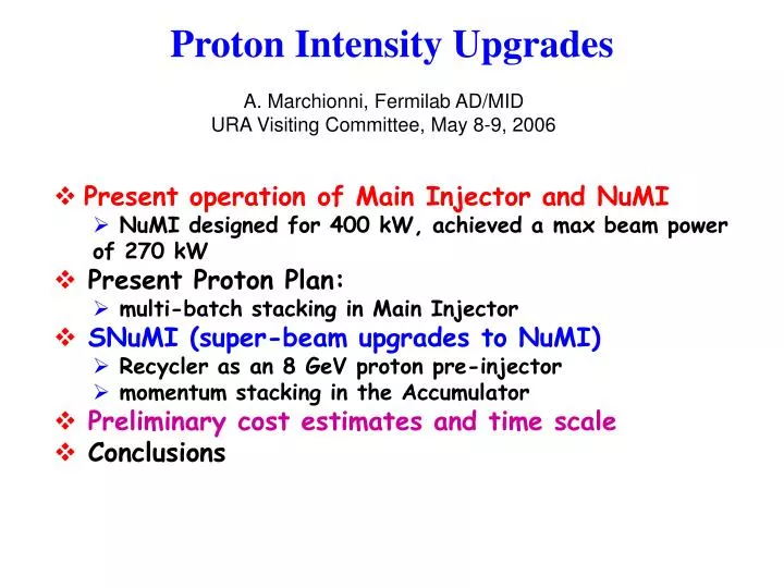
Proton Intensity Upgrades. A. Marchionni, Fermilab AD/MID URA Visiting Committee, May 8-9, 2006. Present operation of Main Injector and NuMI NuMI designed for 400 kW, achieved a max beam power of 270 kW Present Proton Plan: multi-batch stacking in Main Injector

E N D
Proton Intensity Upgrades A. Marchionni, Fermilab AD/MID URA Visiting Committee, May 8-9, 2006 • Present operation of Main Injector and NuMI • NuMI designed for 400 kW, achieved a max beam power of 270 kW • Present Proton Plan: • multi-batch stacking in Main Injector • SNuMI (super-beam upgrades to NuMI) • Recycler as an 8 GeV proton pre-injector • momentum stacking in the Accumulator • Preliminary cost estimates and time scale • Conclusions
Decay Pipe ’s to Soudan The Main Injector and the rest of the complex SY120 pbar production target NuMI extraction line
NuMI extraction Lambertsons The NuMI primary proton line Total length ~ 350 m Recycler NuMI line Main Injector MI tunnel bringing the protons to the correct pitch of 58 mrad trim magnets bending down by 156 mrad final focus
NuMI Primary Proton Line 35 mm aperture 95% beam size 7 mm Specifications: fractional beam losses below 10-5 Large aperture line !
Present operation of Main Injector & NuMI • Main Injector is a rapid cycling accelerator at 120 GeV (presently running at 205 GeV/s) • 1.467 s cycle time (for 1 batch injection) • up to 6 proton batches (~ 51012 p/batch) are successively injected from Booster into Main Injector at 15 Hz • Main Injector has to satisfy simultaneously the needs of the Collider program (anti-proton stacking and transfers to the Tevatron) and NuMI • Mixed mode: NuMI & anti-proton stacking (2 s cycle time) • two single turn extractions within ~ 1 ms: • 1 slip-stacked batch to the anti-proton target • 5 batches to NuMI (~2.5×10¹³ ppp) in ~ 8 s • NuMI only (2 s cycle time) • 6 Booster batches extracted to NuMI (~3×10¹³ ppp) in ~ 10 s • NuMI design values: 41013 ppp every 1.9 s 400 kW
30 20 Power (kW) Protons per pulse (1012) 100 10 May 1 ‘05 March 1 ‘06 May 1 ‘05 March 1 ‘06 NuMI first year running 300 200 1.4E20 pot integrated Peak values • max beam power of 270 kW stably for ~ ½ hour • peak intensity of 3×10¹³ ppp Averages over the last months • beampower 170 kW • proton intensity 2.3×10¹³ ppp • cycle spacing 2.2 s
Booster performance and projections Projections Booster performance ’05/’06: ~ 6.5×10¹⁶ protons/hr
Merged bunch train in MI E 2nd Batch 1st Batch Decelerate Accelerate Time 2nd Booster Batch 1st Booster Batch Injected into MI Slip-stacking • A scheme to merge two Booster batches to double proton intensity on pbar production target K. Koba Seiya et. al., PAC2003 • during last year achieved 8×10¹² protons on the anti-proton target
Multi-batch slip-stacking in MI • While running in mixed mode, it is possible to slip-stack 4 out of the 5 NuMI batches, in addition to a slip-stacked batch for the anti-proton source • final phase of the present Proton Plan: • 360 kW, 3.2×10²⁰ protons/year to NuMI Low intensity test I. Kourbanis, K. Seiya
Main Injector parameters • design acceleration rate of 240 GeV/s • presently there is enough RF power to safely accelerate 61013 protons/cycle at a maximum rate of 205 GeV/s • a t-jump system and an upgrade of the RF system are the major modifications that would allow to raise the intensity up to 11014 protons/cycle
Main Injector RF system I. Kourbanis, beams-doc-1927 • The current MI RF system consists of 18 stations • presently each cavity is driven by a single Eimac 4CW150000E power tetrode mounted directly on the cavity providing up to 175 KW (operationally) • cavity impedance, at energies above transition, is ~ 500 KΩ (R/Q=104) • with slip stacked beam we need a moving bucket area ≥1.8 eV-s after transition • presently enough power to stably accelerate up to 6×10¹³ ppp at 205 GeV/sec (1.467 s cycle time) • We have a total of 3 spare RF cavities allowing the expansion to 20 stations • adding 2 more RF stations will allow us to increase the max accel. rate to 240 GeV/sec reducing MI cycle time to 1.333 s • Each cavity has an extra port available for the installation of a second power tube (up to ~ 1×10¹⁴ ppp)
SNuMI stage 1: 700 kWRecycler as an 8 GeV proton pre-injector S. Nagaitsev, E. Prebys, M. Syphers ‘First Report of the Proton Study Group’, Beams-doc-2178 • After the Collider program is terminated, we can use the Recycler as a proton pre-injector • Booster batches are injected at 15 Hz rep rate • if we use the Recycler to accumulate protons from the Booster while MI is running, we can save 0.4 s for each 6 Booster batches injected • 6 batches (5×10¹² p/batch) at 120 GeV every 1.467 s 390 kW • Recycler momentum aperture is large enough to allow slip-stacking operation in Recycler, for up to 12 Booster batches injected • 6 batches are slipped with respect to the other 6 and, at the time they line up, they are extracted to MI in a single turn and there re-captured and accelerated • ~4.7×10¹² p/batch, 95% slip-stacking efficiency • 5.4×10¹³ ppp at 120 GeV every 1.467 s 700 kW
Multi-batch slip-stacking in Recycler I. Kourbanis, K. Seiya, beams-doc-2179 • Recycler momentum aperture measured to be 1.5% full span • Two RF systems required each at a frequency of 52809000±1300 Hz, producing 150 kV each • Transient beam loading compensation is crucial • R/Q smaller than 100
SNuMI stage 2: 1 MWMomentum stacking in the Accumulator D. McGinnis, Beams-doc-1782, 2138 • After the Collider program is terminated, we can also use the Accumulator in the Anti-proton Source as a proton ring • after acceleration in the Booster, beam will be transferred to the Accumulator • the Accumulator was designed for momentum stacking • momentum stack up to 4 Booster batches every 267 ms • limit Booster batch size to 4×10¹² protons • 84×0.08 eV-s 84×0.38 eV-s (19% emittance dilution) • Box Car stack in the Recycler • load in a new Accumulator batch every 267 ms • place 6 Accumulator batches sequentially around the Recycler • Load the Main Injector in a single turn • 9.5×10¹³ ppp in MI every 1.6 s 1.1 MW
Charge for SNuMI stage 1, 700 kW R. Dixon, February, 2006 • I would now like you to develop a conceptual design and cost estimate for a modification to the Recycler and Main Injector to provide a 0.7 MW 120 GeV beam to NuMI after the collider program ends. The main feature of this upgrade is to convert the Recycler into a proton accumulator, shortening the Main Injector cycle time from 2.2 seconds to 1.5 seconds. • The conceptual design should include modifications to the Recycler and the Main Injector such as the removal of pbar specific devices, modification of injection and extraction lines, slip stacking, collimation, dampers. • The conceptual design should include all NuMI target hall modifications required operate the facility at 0.7 MW such as the target, horns, and the decay pipe cooling system. • The conceptual design should consider all aspects of high power acceleration and transport; beam stability, RF power, instrumentation, collimation, transport and targeting, radiation shielding, groundwater and air activation for all facilities. • The conceptual design and cost estimate should be documented in a report suitable for presentation to the Directorate in the fall of 2006.
Beam physics & Instability issues B. Zwaska Radiation safety for RR, MI and NuMI T. Leveling • Shielding assessment • Ground water protection • Surface water protection • Activated air emission • Residual activation • MI & RR Impedance measurements • Longitudinal & transverse instabilities and damping • Electron cloud NuMI Upgrades M. Martens Recycler Ring Upgrades P. Derwent • Primary proton beam (S. Childress) • Power supplies, magnet cooling and NuMI kickers for 1.5 s operation • Target & horns (J. Hylen) • Target and Horns • Water cooling of stripline • Fabrication of stripline section for ME beam • Cooling of target chase • Decay pipe & hadron absorber (B. Lundberg) • Decay pipe upstream window • Decay pipe cooling • Eventual upgrade Hadron Absorber • Recycler Ring modifications (Cons Gattuso) • Removal of pbar specific devices • Injection/extraction lines • Kickers • Slip-stacking schemes (K. Seiya) • Recycler Ring 53 MHz RF system (D. Wildman) • Dampers (P. Adamson) • Instrumentation (P. Prieto) • BPM upgrade Booster E. Prebys • Booster rep rate up to 9.3 Hz • Beam quality SNuMI 700 kW organization Main Injector I. Kourbanis • Additional RF cavities Engineering Support R. Reilly • NuMI Target Hall and • components (2 FTE) • Proton delivery (1 FTE) • Support from PPD on FEA
Recycling the Recycler Injection line from MI-8 to RR • Take anti-proton specific devices out • Build new transfer lines • direct injection into RR • new extraction line at RR-30 • rework RR-30 straight section • 53 MHz RF system for Recycler • Instrumentation Extraction line in the 30 section Have preliminary designs and cost estimates
Upgrading NuMI • Issues: • running the primary proton line at higher rep-rate • removing larger heat load in the target chase • thermal shock, heat damage and radiation damage to target and horns • thermal shock to decay pipe window and beam absorber • radiation safety • Off-axis neutrino beam better optimized in ‘Medium Energy’ configuration • target less constrained, it is external to the horn ! Medium energy target Engineering support freed up after shutdown to look into these issues for the major NuMI components
SNuMI preliminary cost estimate • Booster: repetition rate upgrade to 15 Hz • Main Injector: RF and shielding upgrades • Recycler: new injection and extraction transfer lines, RF systems • Accumulator: new injection and extraction lines, new RF systems • NuMI: upgrade primary proton line, new target and horn, target chase cooling, installation of Helium bags, work cell upgrade Includes only M&S, no inflation, no contingency
SNuMI preliminary time scale • Main assumptions: • 2010: year-long shutdown to complete all upgrades required for 1 MW • 2011: start using the Recycler at 400 kW and gradually implement slip-stacking over multi-batches up to 700 kW beam power • 2012: short shutdown to fix eventual problems and start momentum stacking in Accumulator, increasing beam power to 1 MW • 2013: run steadily at 1 MW • Efficiency factors: • Complex uptime: 0.85 • Average to peak performance: 0.9 • NuMI line uptime: 0.9
The power of neutrino beams J-Park: path to a few MW facility is being studied
Conclusions • The Main Injector has presently operated up to ~ 3.15×10¹³ ppp and at a maximum beam power of 270 kW • With the termination of the Collider program, a set of upgrades to the accelerator complex can increase the beam power up to 1 MW • the use of the Recycler as a proton pre-injector, together with multi-batch slip-stacking, allows to reach a power of 700 kW • adding 2 RF cavities in MI allows 10% reduction of MI cycle time • momentum stacking in the Accumulator allows to increase the beam power to 1 MW • A project is being developed to achieve these goals, addressing all issues both in the accelerator complex and the NuMI beam-line • a conceptual design and cost estimate for the 700 kW first phase is due in the fall of 2006
Main Injector ramps Increasing the max. pdot to 240 GeV/sec from 205 GeV/sec reduced the MI cycle time by 13%.
Main Injector RF system II I. Kourbanis, beams-doc-1927
7.2×10¹³ 5.4×10¹³ 3×10¹³ Electron cloud effects ? • Electron Cloud can limit the performance of high-power positron, proton, and ion machine • Simulations suggest that MI might be near a threshold Bunch intensity M. Furman (LBL) FERMILAB-PUB-05-258-AD
Activities in Electron Cloud • started investigation of dynamic pressure rises around the ring using ion pumps • presently installing two ion gauges at different locations (better bandwidth ?) • borrowed an electron detector from Argonne (RFA type) • being installed • directly measures electron current incident on the beampipe • Collaboration with LBL on simulations – M. Furman, J. Corlett, B. Zwaska, X. Zhang • Collaboration with SLAC on SEY – B. Kirby, W. Chou • directly measures secondary emission yield of MI beam-pipe • Parallel measurements effort in Tevatron – X. Zhang • will allow testing with different beam parameters