Download
1 / 45
480 likes | 886 Views
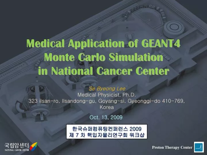
Medical Application of GEANT4 Monte Carlo Simulation in National Cancer Center. Proton Therapy Center. Se Byeong Lee Medical Physicist, Ph.D. 323 ilsan-ro, Ilsandong-gu, Goyang-si, Gyeonggi-do 410-769, Korea. Oct. 13, 2009. 한국슈퍼컴퓨팅컨퍼런스 2009 제 7 차 핵입자물리연구회 워크샵.

E N D
Medical Application of GEANT4 Monte Carlo Simulation in National Cancer Center Proton Therapy Center Se Byeong Lee Medical Physicist, Ph.D. 323 ilsan-ro, Ilsandong-gu, Goyang-si, Gyeonggi-do 410-769, Korea Oct. 13, 2009 한국슈퍼컴퓨팅컨퍼런스 2009 제 7 차 핵입자물리연구회 워크샵
History1989. 12. Plan to establish NCC formulated by Ministry of Health and Welfare1997. 7. Construction of NCC Hospital building completed2000. 10. NCC started clinical care services 2005. 2. Proton Therapy Facility Installation 2005. 10. First Beam Production2007. 3. First Proton treatment start 2009. 9. ~ 500 patients treated in Proton Therapy Facility Overview of NCC
Equipments in Proton Therapy Center(PTC) Linac : 4 CT scanner: 2
Proton beam facility in PTC • Proteus 235 Specification • Weight : 220 ton Height : 210 cm Diameter : 434 cm • Energy : 230MeV • Max. extracted beam current : 300nA • RF frequency :106 MHz
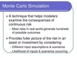
Proton Therapy Characteristic of proton (Bragg Peak) Proton is quite different from x-ray in terms of energy transfer. As it enters a cancer patient’s body through skin and tissue, it releases a relatively low dose of energy before it reaches the target. It, however, hits the targeted tumor by depositing the biggest dose of energy on it, then suddenly stopping its activity afterwards. The point where the highest energy is released is called as the Bragg Peak.
Motivation of MC Simulation Study for Radiation Therapy • Radiation Treatment Planning : Accurate dose calculation ? • Radiation Shielding : Patient & worker safety ? • Patient Simulation (Respiratory gating) : 4D Dose distribution ? • Beam Detector Study : Design study, QA ? Monte Carlo Simulation
Proton Beam modulation methods • Passive mode Dynamic mode
MC simulation of Proton Beam System • Modeling • Modeling Nozzle • Modeling Treatment scheme • User interface for M.C set-up • Convalgo (“Conversion Algorithm” by IBA) interface • Validation • Geant4 physics test on CSDA rangeand non-elastic interaction probability • Bragg peaks comparison • Conversion function (Range2MCEnergy) • Results & Applications • SOBP reproduction
1. Modeling - nozzle Framework libraries User applications
weighting_table Current controlled by Cyclotron Stop Digit Modeling – treatment scheme (passive scattering) Beam Current Modulation (BCM) → Total 52 BCM records Stop digit determines width of SOBP Weighting_table stands for cyclotron current to determine flatness of SOBP /TCS/passive/BCM TR2_B6_1 144 1000/TCS/StartIrradiation
Measurement Rp (Range in Patient), SOBP Monte Carlo Scatterers setting Variable collimator opening R.M wheel with BCM database Snout positioning Cyclotron energy, current ... 2. User Interface – ConvAlgo interface input CONVALGO output Treatment Control System (TCS) - not clinical mode /GTR2/SNT/type 250 /GTR2/SNT/aperture/rectangle open /GTR2/SNT/aperture/rectangle Lx Ly Ox Oy #Geant4 kernel initialize /run/initialize /GTR2/FS/lollipops 9 5 /GTR2/SS/select 3 /GTR2/RM/track 5 /GTR2/RM/angle 80.26 /GTR2/VC/setVxVy cm 14.2 15.2 /BTS/particle proton /BTS/energy E MeV 181.8 1.2 /BTS/geometry mm 3 5 /BTS/emittance G mm 1.5 /TCS/passive/BCM TR2_B6_1 144 1000/TCS/StartIrradiation BCM pattern Init. Beam configuration BTS : BeamTransportSystem, TCS : TreatmentConstrolSystem Nozzle configuration
Validation – M.C energy MEAN ENERGY SIGMA sigma(R) = a - b*R E(r) = exp(a+b*log(r)+c*pow(log(r),2) /BTS/energy L cm 15.4 Or /BTS/energy E MeV 181.8 1.2
4. Results – action animation Snouts re/extraction → Gantry rotation → 1st scatter lollipop → 2nd scatter positioning → Variable collimator opening → RM spinning & irradiation up to Stop digit
Results – SOBP simulation Histogram: M.C Circle : Measurements preliminary DICOM I/O & Viewer : gMocren (geant4.kek.jp/gMocren)
DICOM Module(under development) - patient : O O O, particle : photon Simulation result viewer : gMocren by (KEK group, japan) soon... Not NCC data ! + proton nozzle (SiS,DS,US)
4D CT-Phase1 6.0 MV +- 0.1 MV ... beam 6.0 MV +- 0.2 MV 4D CT-Phase10 energy MLC patient CT = nozzle 12 nA 10 nA Gantry angle current 40 ° 30 ° 31 ° 50 ° 32 ° = ... ... From Advanced Oncology Center, Inc (http://aoctr.com) target X-ray Treatment MC simulation 1 (Linac ) Example: Intensity Modulated Radiation Therapy (IMRT) http://www0.sw.org/videos/RadOnc/RadOnc.wvx To produce a field Dynamic MLC opening with concurrent beam current modulation
Field0 ... /run/initialize Idle> /linac/rotation 10 deg #Field0, fraction 0 at Time =0 Idle> /linac/mlc/open leaf0 2 cm Idle> /linac/mlc/open leaf1 1.3 cm ... Idle> /linac/mlc/open leaf100 1.3 cm Idle> /run/beamOn 1000 ... #Field0, fraction 1 at Time = 1 Idle> /linac/mlc/open leaf0 2 cm Idle> /linac/mlc/open leaf1 1.3 cm ... Idle> /linac/mlc/open leaf100 1.3 cm Idle> /run/beamOn 2300 Idle> .... Idle> /linac/rotation 15 deg #Field1, fraction 0 at Time ... X-ray Treatment MC simulation 2 (Linac ) {Geant4 user commands for IMRT} ... Idle> /linac/mlc/sequence LeafSeqeunce.dat Idle> /linac/StartIrradiation Hopefully Although Geant4 supports the dynamical set-up of modality through user commands, we wanted to put this functionalities into development side (not user side) and execute simulation automatically. % To simulate a treatment, /run/beamOn method might be called more than hundred times with change of MLC opening before every run
G4int start_lut = 0 ; G4int stop_lut = _LUT->GetLUTSize(); for(G4int i=start_lut; i < stop_lut ; ++i){ _LUT->ComputeNozzle(i); _LUT->ComputeBeam(i); _LUT->ComputePhantom(i); … this->BeamOn( _LUT->GetNumberOfParticles(i)); } X-ray Treatment MC simulation 3 (Linac ) The StartSequentialRun() method was added to G4RunManager to automatically 1. invoke ComputeXXX methods defined in user class of VSequentialRunParameterisation 2. perform individual simulations by referring number of participant particles until Look-up table being empty Because Sequential RunManager is independent (no needs of re-writing) of user application, Internally generating look-up table for specific application is our key approach.
copyNo seqNo GenerateLUT() ComputeDimension(30) ComputeTransformation(30) CopyNo=30 update location ComputeBeam(30) ComputeNozzle(30) ComputePhantom(30) CopyNo=31 X-ray Treatment MC simulation 4 (Linac ) % The sequence number (seqNo) : a moment on time-sequence <=> the copy number of G4PVParameterisation : an identifier as a part of geometrical structure. TheVSeqentialRunParameterisationclass was devised to - generate a look-up table having dynamical information of constituent as function of time-sequence - provide the Geant4 kernel with interfaces to change the conditions by referring the look-up table • The pure virtual methods ofVSequentialRunParameterisation • GenerateLUT() generates Look-Up table • GetLUTSize() returns the size of Look-Up table • GetNumberOfParticles(G4int seqNo) returns number of particles per individual simulation • ComputeNozzle(G4int seqNo) changes nozzle set-up • ComputeBeam(G4int seqNo) changes beam condition • ComputePhantom(G4int seqNo) change target phantom set-up
... Isotope Treatment MC simulation 1 (Brachytherapy ) Objective: final dose distribution made of isotope seeds which have different energy, current, and position Features: 1. does not need a nozzle 2. Point like isotope source 3. Photons are emitted equally in 4-pi direction from source 4. The number emitted photons is configurable 5. The position of isotope source is configurable User Input: ascii file (IMBT_sources.dat) # Position (X, Y, Z) cm Energy (MeV) Weighting 0 1 0 0.7 1 0 2 0 0.7 1 0 3 0 0.7 3 .. 0 10 0 0.7 5
Isotope Treatment MC simulation 2 (Brachytherapy ) Simulation preparation Action Result
Relative absorbed dose in water phantom • Incident Energy : 230 MeV • Each line presents relative absorbed dose as a function of water depth. • Dose contribution by alpha, d, t, is less than 1% of total dose. • In the case of secondary particle, dose contribution of each slice is from 2% up to 12% before the bragg peak region. • Absorbed dose beyond the bragg peak is mostly caused by secondary proton. NCC –MC Study
BC408 M.C study : 1/4 • Purpose : the accurate simulation study will help to design and construct a dosimetry device utilizing the BC408 scintilator
BC408 M.C study : 2/4 • Simulation of Material properties : Optical photon distribution Total light output vs proton energy CSDA Range in BC408 vs proton energy
BC408 M.C study : 3/4 • Quenching effect implementation of G4Scintillation (G4Scintillation.hh,cc) process
BC408 M.C study : 4/4 • Comparison : Eclipse RTP calculation data vs M.C simulation data validated proton beam resolution : 2mm in X,Y and 1mm thickness
Grid Computing (KISTI, FKPPL VO) Definition by Ian Foster - Computing resources are not administered centrally. - Open standards are used. - Non-trivial quality of service is achieved.
FKPPL VO Testbed VOMS WIKI CE UI CE LFC WMS SE SE FKPPL VO IN2P3 KISTI By courtesy of S.W.Hwang in KISTI.
JOB Performance test on GRID 1/2 By courtesy of S.W.Hwang in KISTI.
From 1 file, ~3.5 hrs on WN of FKPPL From 589 files, 589 files sucessfully generated among total 99*7 (693) jobs JOB Performance test on GRID 2/2 resolution : 2mm in X,Y and 1mm thicknes I immediately submit parametric job after initializing the proxy
Summary & Future Plans • Geant4 MC simulation(Low Energy) is useful for Medical applications (Radiation Therapy). • We are developing Dose Calculation tools with the MC simulation method (Geant4) • Preparing for the International Collaborations - FKPPL LIA ( France-Korea Particle Physics Lab.) - KEK Geant4 Team (Tsukuba Japan)