Download
1 / 29
290 likes | 409 Views
855 N. Wolfe Street, Building L-1. P RESENTED O N : May 4, 2007. H EATHER A. S USTERSIC. S TRUCTURAL O PTION. Biomedical Research Facility– offices and laboratories. 1 st of 5 Research Buildings in New East Baltimore Development. 31 Acre Science & Technology Park 80 Acres total

E N D
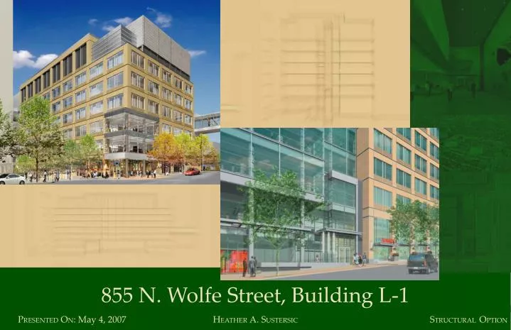
855 N. Wolfe Street, Building L-1 PRESENTED ON: May 4, 2007 HEATHER A. SUSTERSIC STRUCTURAL OPTION
Biomedical Research Facility– offices and laboratories 1st of 5 Research Buildings in New East Baltimore Development • 31 Acre Science & • Technology Park • 80 Acres total • $800 million urban • redevelopment • 1,200 mixed housing units • 1.1 million ft2 in • 5 buildings • 277,000 ft2 in • Building L-1 • Pedestrian bridge to Johns Hopkins University acts as “gateway” Size: 277,000 ft2 Height: 8 stories, 143'-5" tall (from lowest grade) Construction: April 2006 to May 2008 Project Cost: $50,000,000 (base building cost) plus $100 to $200 per square foot (finishes) Envelope: Precast concrete panels with punched windows and glass curtain walls HEATHER A. SUSTERSIC
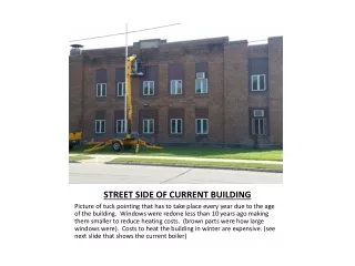
Important Design Issues for Building L-1 • Structural Concerns: • 8,000 μ-in/sec vibration criteria • 100 psf live load • 47’ - 30’ - 47’ typical 3 span configuration • Construction Concerns: • Small site • Cost • Building Wall Envelope Concerns: • Water Management • Air Infiltration Structural redesign in concrete. Cost and schedule analysis of redesign. Evaluate building wall envelope. HEATHER A. SUSTERSIC
Success of thesis project measured by: • Structural Concerns: • Meet gravity load & vibration criteria • Thinner floor sandwich • Resist lateral loads • Construction Concerns: • Workable site & schedule • Save $ • Building Wall Envelope Concerns : • Wall envelope is not prone to failure HEATHER A. SUSTERSIC
Existing system is composite steel with braced frames. Typical Floor Plan with Braced Frames: HEATHER A. SUSTERSIC
Existing system is composite steel with braced frames. Existing Typical Bay: Composite Properties: HEATHER A. SUSTERSIC
Existing system is composite steel with braced frames. Personal Photo: Taken January 4th, 2007 HEATHER A. SUSTERSIC
Existing system composite steel beams are large. Personal Photo: Taken January 4th, 2007 HEATHER A. SUSTERSIC
Proposed system is a combination of PT and regular concrete. Proposed Typical Floor Plan with Shear Walls: HEATHER A. SUSTERSIC
Proposed system is a combination of PT and regular concrete. 0’-7 ½” 2’-0” 7’-0” Proposed Typical Beam/Slab Sizes: One-way regular concrete slab #5 @ 8” end span #5 @ 12” interior span Post-Tensioned wide, shallow beams Worst case: (44) ½” φ lo-lax strands with (25) #5 bars Typ. case: (26) ½” φ lo-lax strands with (25) #5 bars Photo taken from: Design Fundamentals of Post-Tensioned Concrete Floors. PTI, 1999. HEATHER A. SUSTERSIC
Proposed system is a combination of PT and regular concrete. Proposed Typical Beam/Slab Sizes: 0’-7 ½” 2’-0” • Controlling Design Parameters: • Slab– cracked section deflection • 2. PT beams– strength/serviceability • requirements 7’-0” Photo taken from: Design Fundamentals of Post-Tensioned Concrete Floors. PTI, 1999. HEATHER A. SUSTERSIC
Proposed system is a combination of PT and regular concrete. PH Low Roof PH 6th 5th 4th 3rd 2nd 1st 6 ksi 4 ksi Interior Spandrel Proposed Typical Column Size: Proposed Typical Shear Wall Size: 20”x20”, fc’ changes HEATHER A. SUSTERSIC
Proposed system is a combination of PT and regular concrete. Depth Comparison of Existing and Proposed Floor Sandwich Note that the two systems differ by 9 ¼”. HEATHER A. SUSTERSIC
STAAD Pro model was created to determine fn • Model Statistics: • 2 ½ bays of typical floor • 7,300 12”x12” plates • Plate thickness matched floor thickness (7.5”, 24”) • Pinned supports HEATHER A. SUSTERSIC
Proposed system exceeds minimum vibration criteria. Vibration Criteria Required: 8,000 μ-in/sec Vibration Criteria Achieved: Depends on tempo HEATHER A. SUSTERSIC
8,000 μips is an acceptable vibration criteria for this project. • Nature of End Use of Building: • Biomedical research • Sensory perception • Infectious diseases • Imaging • Office/Administrative Source: www.stanford.edu/group/bioconfocal/ HEATHER A. SUSTERSIC
The site is very small– concrete requires less site space than steel. Site Trailers & Laydown Area Building Footprint Photo: Courtesy of Matt Scott, Project Engineer, Hensel Phelps/Commercial Interiors HEATHER A. SUSTERSIC
The site is very small– concrete requires less site space than steel. Site Trailers & Laydown Area 180’ tall tower crane with 181’ boom radius Personal Photo: Taken on January 4th, 2007. HEATHER A. SUSTERSIC
Site Trailers Site Boundary Concrete Truck Concrete Pump Rebar Staging ~15’ Crane 13’ 10’ Deliveries 10’ HEATHER A. SUSTERSIC
Concrete will be pumped to the superstructure. Photo: Courtesy of Corinne Ambler, PSU AE Student HEATHER A. SUSTERSIC
Floor by Floor Concrete Construction Sequencing Form Rebar/Ducts Pour Post Tension HEATHER A. SUSTERSIC
Schedule almost the same for new system. HEATHER A. SUSTERSIC
Cost savings achieved with new system. • Existing Structural System Cost Breakdown: • 1. Structural Steel (including metal deck) $5,666,000 • 2. Superstructure Concrete $1,700,000 • 3. Sprayed-on Fireproofing $755,000 • 4. Foundation Concrete (drilled piers) $2,600,000 ($1,300,000) • Existing Structural System Total: $10,721,000 • 5. Building Skin $55 per SF • New Structural System Cost Breakdown: • 1. Superstructure Concrete (w/placing & forms) $6,246,263 • 2. Foundation Concrete $2,990,000 • New Structural System Total: $9,236,263 • 3. Building Skin Savings (height decrease of 5’) $222,000 HEATHER A. SUSTERSIC
Building wall envelope works well. • Curtain Wall Details • Wet glazed • Constructability • Moisture Management Kawneer 1600 System 2 Assembly Detail Diagram Available at: http://www.alcoa.com HEATHER A. SUSTERSIC
Building wall envelope works well. • Punched Window Details • Dry glazed • Unitized System • Moisture Management TRACO TR-2800 System Detail Available at: http://www.traco.com/pdupg/pd_2800.htm HEATHER A. SUSTERSIC
A full-scale mock-up should be constructed to test interfaces. • Potential problems: • Reentrant corners • Punched window/ • curtain wall/ • precast interface • Improper installation HEATHER A. SUSTERSIC
Success of thesis project measured by: • Structural Concerns: • Meet gravity load & vibration criteria • Thinner floor sandwich • Resist lateral loads • Construction Concerns: • Workable site & schedule • Save $ • Building Wall Envelope Concerns : • Wall envelope is not prone to failure HEATHER A. SUSTERSIC
Special Thanks To The Project Team: Structural Engineer: Civil Engineer: Owner/Developer: Architect: Construction Managers: MEP Engineer: Lighting Consultant: Architect of Record: Project Renderings and Floor Plans provided by Forest City Enterprises, Unless Otherwise Noted Several other companies also participated. HEATHER A. SUSTERSIC
Questions? HEATHER A. SUSTERSIC