Download
1 / 42

E N D
1. Chapter 10: Electrical Systems BAE 599 - Lecture 10 Part A
2. Functional Elements Engine starting
Ignition
Lighting (Work and Safety)
Sensing, display and control
Controlled environment
Accessories (windshield wipers, entertainment, and communications)
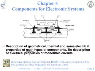
3. Fig. 10.1 Components of Electrical Systems
4. Batteries Primary electrical storage device on off-road equipment.
Is discharged upon starting, and recharged during operation.
Lead-acid batteries are the primary source of electrical power in off-road equipment.
5. Fig. 10.2 Lead-Acid Battery Diagram
6. Fig. 10.3 Circuit Model for 12 V Battery
7. Table 10.1 Theoretical Cell Voltages
8. Battery Construction ABS plastic case
Lead calcium alloy plates � reduced gassing and water loss
Earlier batteries used lead antimony alloys requiring more maintenance
Glass fiber matt used to separate plates and add strength
9. Ratings Cold Cranking Amps � current delivered for 30 s duration at temperatures of -29 to -18 C, with an end voltage of at least 1.2 V/cell.
Reserve Capacity � duration for which battery can deliver 25 A at 27 C with ending cell voltage of 1.75 V or better.
10. Sizing Batteries Starting loads provide the greatest demand to battery charge.
Charging systems must be able to recharge battery in time for next starting cycle.
Energy efficiency of a battery is the ratio of discharge energy to charging energy � for most batteries this is 75%.
11. Charging Systems Engine driven alternator with integral voltage regulator
Stationary coils (stator) with rotating coil (rotor).
Claw pole is the most common design.
12. Fig. 10.4 Claw Pole Alternator
13. Fig. 10.5 Diode Bridge
14. Diode Bridge Positive current from stator flows from terminal �C� of bridge to �A�
Blocked from flowing to terminal �B�
Only positive current flows through
Negative current is returned to stator
When driven with negative current, current flows from terminal �D� upwards to �B�
15. Diode Bridge Bridge switches connection to stator
DC current with significant ripple
Three sets of poles, spaced 120 degrees apart, are utilized to smooth ripple.
More efficient alternator from overlapping sinusoidal current waves
16. Fig. 10.6-7 Three Phase Rectification
17. Fig. 10.8 Charging Circuit
18. Alternator Sizing Alternator performance curves can be utilized for sizing.
Alternator must be capable of meeting the long-term load demands, plus recharging the battery.
Long-term load demands include: fuel pump, head lamps, work lamps, instrument panels, control systems, and battery charging.
19. Fig. 10.9 Alternator Performance Curve
20. Alternator Sizing Alternator should be able to supply 130-150% of long-term loads at idle engine speed.
Estimate starter load for recharging (2 kW for 15 s).
Assume a system operating voltage of 14 VDC.
21. Table 10.2 Worst-Case Loads
22. Starting Systems Electric motor
Engagement mechanism with spur gear
Spur gear to ring gear ratio of 10:1 to 15:1 is common
Gear reduction if necessary � some starters utilize a planetary reduction to increase torque
23. Fig. 10.10 Starter Cutaway
24. Starter Motor Typical DC motor design with field coils, armature, and brushes
Field windings are either series-wound or shunt-wound.
Series-wound motors have high locked-rotor/low-speed torques.
Change-over relay is required in 24 V starter circuits.
25. Fig. 10.11 Starter Performance Curves
26. Fig. 10.12 Schematic of 12/24 Starting Circuit
27. Starter Selection Considerations Engine torque is a function of
Engine must rotate at 80-200 rpm without starting aid, and 60-140 rpm with starting aid.
Maximum voltage drop trough battery cables should not exceed 0.1 V for 12 V systems and 0.17 V for 24 V systems.
28. Fig. 10.13 Engine and Starting Torque Curves
29. Staring Circuits Safety interlocks to prevent inadvertent starting when shields have been removed or when the transmission is in gear.
Design should discourage or prevent electrical connections at starter motor solenoid or starter relay to prevent operators from being run over.
30. Fig. 10.14 Safety Interlocks
31. Lighting Purpose of lighting includes safety, instrument and work functions.
Safety � beacon lights, tail lights, turn signal lights, and marker lights per ASAE S279.11, SAE 1029, and ISO 12509.
Homologation � process of insuring that equipment exported to other countries conforms to applicable standards
rr
32. Lighting Work lights illuminate surfaces that must be seen in the dark to permit vehicle operation.
Incandescent and halogen lights are common, the latter is beginning to dominate the market.
High-intensity discharge systems are optional.
Light efficiency: incandescent 10-18 lm/W, halogen 22-26 lm/W, and gas discharge 85 lm/w.
33. Power Distribution Cable/wire sizing factors: mechanical strength, temperature rise, voltage drop, and connectors.
Minimum cable/wire size of 0.8 mm2 in harness or 1 mm2 for area susceptible to damage are recommended.
Also must consider requirements for abrasion resistance, bend strength and fluid resistance for battery and primary cable (SAE J1127 and J 1128.
34. Table 10.3 Thermal Protection Wire Size
35. Table 10.4 Steady-Sate Capacity
36. Voltage Drop Calculations Resistance, R,
where A is the cross-sectional area, l is the length, and r is the resistivity of the conductor.
37. Voltage Drop Calculations Resistivity at another temperature, rt,
where T is he temperature of the material, Tbase is the base temperature of the material, a is the temperature coefficient of electrical resistivity, and rbase is the resistivity of the material at the base temperature.
38. Table 10.5 Steady-State Thermal Capacity
39. Specific Resistance for Nominal Wire Size Specific resistance, rs, can be determined as,
where DV is the voltage drop, l is conductor length, and i is current.
40. Table 10.6 Specific Resistance of Copper Cables
41. Implement Connection ASAE S279.11 requires an implement connector for directional signals, work lamps, tail lamps, and an auxiliary power source.
Connector should conforms to SAE J560, to be superseded by ISO 11783.
42. Homework Set No. 9 Do problems 10.1 through 10.7 at the end of Chapter 10 for next Tuesday.