Download
1 / 21
210 likes | 347 Views
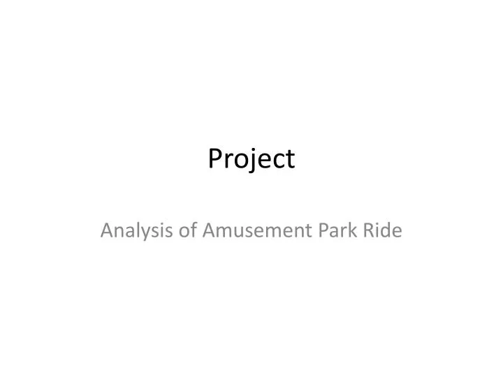
Project. Analysis of Amusement Park Ride. 6. 8. 4. 7. 1. 6,7. 5. 2. 5. 8. 3. 4. 1. 0. 0. 4. 2,3. 9 bodies, 8 revolute joints, 1 prismatic joint M = 6(9-1) – 5(9) = 3. axes of Hooke joint are perpendicular. 180”. 5 S 6. 3 S 4. 7 S 8. 8. 4. 7. 6. 1. 6 S 7. 7 S 8.

E N D
Project Analysis of Amusement Park Ride
6 8 4 7 1 6,7 5 2 5 8 3 4 1 0 0 4 2,3 9 bodies, 8 revolute joints, 1 prismatic joint M = 6(9-1) – 5(9) = 3
axes of Hooke joint are perpendicular 180”
5S6 3S4 7S8 8 4 7 6 1 6S7 7S8 1S2 6,7 3 5 2 2S3 5 8 8S0 0S1 4S5 4 1 0 4 1S2 2,3 0
5S6 3S4 a7 a6 a2 7S8 8 a5 4 7 6 1 6S7 7S8 1S2 6,7 3 5 2 a4 2S3 a3 5 8 8S0 0S1 4S5 4 a8 1 0 4 1S2 2,3 a1 0
5S6 3S4 a7 a6 a2 7S8 8 a5 4 7 6 1 6S7 7S8 1S2 6,7 3 5 2 a4 2S3 a3 5 8 8S0 0S1 4S5 4 ZF a8 1 0 4 XF 1S2 2,3 a1 0
Distance along ZF axis between origin of fixed coordinate system and origin of link 8 coordinate system is 654 – 2(9) = 636 inches.
Z8 6,7 7S8 5 8 X8 8S0 4S5 4 ZF a8 1 0 4 XF 2,3 0
Problem Statement • given • constant mechanism parameters • angle φ1 and φ8 (angle from a8 to xF about 8S0) • angular velocities • angular accelerations • location of rider (point A) in 4th coordinate system • find • position of point A measured in fixed coordinate system • linear velocity and linear acceleration of point A measured in fixed coordinate system
Procedure • do position analysis • do velocity analysis • do acceleration analysis
Position Analysis • To resolve the extra degree of freedom, choose 0φ1 + 1θ2 = 180. This will keep a2 pointed opposite to xF. • Determine the location of the center of the ball and socket joints as measured in the fixed coordinate system. This will give F(4S5) and the distance 4S5. • Get . The second column represents Fy4, which is along F(4S5) and thus known.
The cosine of 3θ4 is determined from the [2,2] element of the array. Select the ‘appropriate’ value for 3θ4, i.e.0 3θ4 . • The corresponding sine and cosine of 2θ3 are determined from the [1,2] and [3,2] elements.
Position Analysis • Get going the ‘other way’ around the chain.
Position Analysis • Get going the ‘regular way’ around the chain. All these terms are now known in terms of given and calculated parameters.
Position Analysis • The angle 6θ7 is obtained from the [3,2] element of the array. (choose one of the inverse cosine values) • The corresponding value for the angle 5θ6 can be determined from the [3,1] and [3,3] elements of the arrays. • The angle (7θ8 + 0φ8) is determined from the [1,2] and [2,2] elements of the arrays.
Velocity Analysis 0 0 • solve 6 scalar equations in 6 unknowns • get • get
Acceleration Analysis 0 0 0 0 0 0 0 0 0 revolute joint prismatic joint Note: Body ‘9’ is body ‘0’.
Acceleration Analysis 0 revolute joint prismatic joint
Acceleration Analysis • solve 6 scalar equations in 6 unknowns • get • get