Download
1 / 18
200 likes | 222 Views
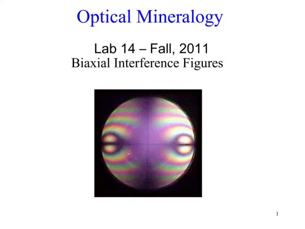
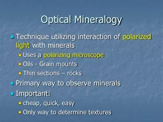
Optical Mineralogy. Optical mineralogy examines the interaction of minerals with visible light. The differences in interaction can be used to identify minerals derive sometimes the conditions in which they have formed

E N D
Optical Mineralogy Optical mineralogy examines the interaction of minerals with visible light. The differences in interaction can be used to identify minerals derive sometimes the conditions in which they have formed The interaction between each mineral and visible light depends on the internal crystal structure of the mineral = optical crystallography
Electromagnetic spectrum & visible portion Violet (400 nm) Red (700 nm) White = ROYGBV (can be separated by dispersion)
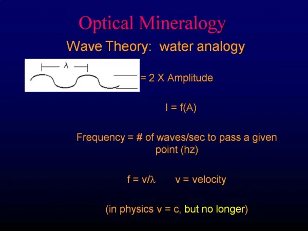
Electromagnetic waves (visible light, X-rays, etc.) Wave Theory Wavelength l = Distance between peaks Frequency = no. of waves/sec to pass a given point (hertz) frequency = v/l , v = velocity f
Pertinent Units Wavelength: nm (=mμ) = 10-9m; old units, Å = 10-8m Frequency: hz (cycles/sec) Energy units (at the atomic scale) are also sometimes used. Energy in eV = ћν, where ћ is Planck,s constant. 1Å is equivalent to 1.24x10⁻²⁴eV.
Polarization Non-polarized (“usual”) light: Each photon vibrates as a wave form in a single plane. Vibration refers to the rise and fall of the sine wave. Light beam is composed of numerous photons, each vibrating in a different plane. Vibration occurs in all directions ~ perpendicular to propagation direction
Polarization Plane of interface = surface of crystal Plane of incidence = T-N-U-V-M-S-O Plane of incidence contains incident, reflected and refracted ray paths as well angles i, l and r
Polarization incoming ray is non-polarized Note symbolization used: Reflected ray polarized perpendicular to the plane of incidence. Refracted ray polarized in plane of incidence. reflected and refracted rays both become polarized
Interference A: Particles in phase if displaced from rest position by same amount in same direction • a1 - a2 - a3 are all in phase • b1 - b2 - b3 are also all in phase (but not with a1…) • particles perfectly out of phase: equal-but-opposite displacement • b1 and c1 are not perfectly out of phase Fig 7-1 Bloss, Optical Crystallography, MSA
Interference path difference (D) = distance between any 2 points on a wave form • usually expressed as xl • D between any 2 points in phase = il (i=any integer) • D between any 2 points perfectly out of phase = ((2i+1)/2) l/2 Fig 7-1 Bloss, Optical Crystallography, MSA
Polarization Our microscopes have two polarizers: • polarizer (below stage) is E-W • analyzer (above stage) is N-S
Ocular Bertrand Amici lens Analyzer Objective Microscope stage Condenser lens Iris diaphragm Polarizer Light source with blue filter
Refraction Incident ray and reflected ray: 1) of incidence i = of reflection r 2) coplanar in the plane of incidence Refracted ray: 1) Slower in water or glass 2) r (refraction) i (incidence) Depends on D v Incident Reflected i r air water r Refracted
Index of refraction For a substance x: nx = vvacuum/vx nair = 1.0003 light is slower in water, glass, crystals Is nwater greater or less than 1? Larger n associated with slower v ! Snell’s Law (1621): ni sin i = nr sin r for two known media (air/water), sin i/sin r = nr / ni = const. So can predict angle change (or use it to determine nr)
Relief of minerals in thin sections: Refractive index of balsam: 1.537 Minerals in thin sections: n >>> 1.537 high relief (positive relief) n = 1.5-1.6, low relief n<<<1.537 high relief (negative relief) First observation parameter of minerals in thin sections!!!: relief
Microscope raised upwards Negative relief Positive relief Becke line method Second observation parameter of minerals in thin sections!!!: refractive index smaller or larger than 1.537 or index of Mineral A is larger or smaller than index of Mineral B
North The Optical Indicatrix A South P P When analyzer inserted = crossed-nicols or XPL shorthand (vs PPL) no light passes extinct, even when the stage is rotated Fig. 6-6 A Fig 6-6 Bloss, Optical Crystallography, MSA P P West East