Download

1 / 59
590 likes | 598 Views
6. Architectural Extraction. Roadmap. Definitions Modeling software architecture with UML Architectural Description Languages Reflexion Models Source-code Views Conclusion and references. Software Architecture is about…. High-level design of the software

E N D
Roadmap • Definitions • Modeling software architecture with UML • Architectural Description Languages • Reflexion Models • Source-code Views • Conclusion and references
Software Architecture is about… • High-level design of the software • Arrangements of larger parts of the system. • (subsystems, large components) instead of classes and objects.
Preliminary Definitions • A system is a set of components that accomplishes a specific function. • A sub-system is a system in its own right whose operation is independent of the services provided by other sub-systems. • A module is a system component that provides services to other components but would not normally be considered as a separate system. • A component is an independently deliverable unit of software that encapsulates its design and implementation and offers interfaces to the out-side, by which it may be composed with other components to form a larger whole.
Some Definitions • [Shaw&Garlan] A Software Architecture defines a system in terms of computational components and interactions amongst those components. • Provides a design plan — a blueprint of the system, and that is an abstraction to help manage the complexity of the system. …The purpose of the software architecture is not only to describe the important aspects for others, but to expose them so that the architect can reason about the design. • …
Standardization: IEEE 1471 Definitions • Architecture is the fundamental organization of a system embodied in its components, their relationships to each other, and to the environment, and the principles guiding its design and evolution. • Architectural description is a set of products that document the architecture. • Architectural View is a representation of a particular system or part of a system from a particular perspective. • Architectural viewpoint is a template that describes how to create and use an architectural view. It includes a name, stakeholders, concerns addressed by the viewpoint, and the modeling and analytic conventions.
Architectural Descriptions • Make the architecture explicit • Can be used for: • Training • Making modifications • Helping Testers • Verification of requirements • Project Management • Operating a system
Architectural Patterns • Capture solution to recurring architectural design problems. • Define a general set of element types and their interactions. • Examples: • Model-View-Controller • Reflection
Architectural Style • [Shaw&Garlan] An Architectural Style defines a family of systems in terms of a pattern of structural organization. More specifically, an architectural style defines a vocabulary of components and connector types, and a set of constraints on how they can be combined. • Dominant architectural pattern = architectural style. • Examples: • pipes and filters • layered architecture
Summary • Lots of definitions • Open for interpretation • Sometimes contradictory • Does not matter as long as: • Make it explicit • Assign semantics • Describe as much as possible
Roadmap • Definitions • Modeling software architecture with UML • Architectural Description Languages • Reflexion Models • Source-code Views • Conclusion and references
Using UML to model architectures • Remember: models are not the end goal, the deployed software system is! • Models are for • Design exploration: understanding existing or creating new parts of the system. • Documentation: communication between new and existing team members. • Do not get stuck in ‘analysis paralysis’. • Top-down approach.
Using UML to model architectures • Key issue: managing complexity • Use case focused modeling: focus on use case or scenario. • Element focused modeling: create views from the perspective of a particular model element. • Level of detail: should be ‘right’: not too abstract, certainly not too detailed. • Controlling the number of models: difference between exploratory models and documentation models. Extract detailed documentation models from code with tools. • Use supplemental textual information: diagrams are not always enough. Complement them with textual descriptions.
Architectural Viewpoint • Template for creating views • Representation of an architecture that can be used to guide construction, manage, explore, train personnel, test, … • Use it for: • Capturing design decisions. • Capturing information about the runtime environment. • Providing constraints on lower-level design. • Providing input to the structure of the development organization. • Designing the system to meet non-functional requirements. • Facilitating communication.
Architectural Viewpoint Structure • Name • Purpose: what is modeled, and what for? • Whenapplicable: in what phase of the lifecycle can it be used? • Stakeholders: what is the audience for this viewpoint? • Modeling conventions: what kind of diagram/technique type is used for the model? • Scalability: How is the diagram used to be scalable? • Relation to other views: what other views have to remain consistent?
List of Viewpoints • Like catalogs of design patters, architectural viewpoints can be collected. • Lists of viewpoints to help with specific architectural development tasks. • Split in different tables: • Conceptual and analysis viewpoints: highly abstracted software descriptions. • Logical design viewpoints: describe the software design. • Environment/Physical viewpoints: focus on the environment and physical aspects of the software.
«External» Other banking Systems Backup system ATM Teller «System» Banking System Web Customer Phone/Pager customer Other branch Sysadmin Loan Officer Example view using Context Viewpoint
Example view using Context Viewpoint • Model complemented with table containing actor descriptions. • Table can also contain more information, such as the estimated data throughput for an actor, critical time periods, … • Model + table are combined in a software architecture document.
Summary: Using UML • Models are not the goal! • Use architectural viewpoints to create architectural views relevant for your system. • Do not use informal notations, but stick to the UML diagram type appropriate for that Viewpoint. • Use Case tools or drawing tools to help making and maintaining the diagrams. • Augment models with textual descriptions that can be more detailed.
Roadmap • Definitions • Modeling software architecture with UML • Architectural Description Languages • Reflexion Models • Source-code Views • Conclusion and references
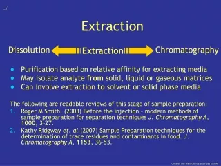
Architectural Description Languages ADLs • formal languages for representing and reasoning about software architecture. • provide a conceptual framework and a concrete syntax for characterizing architectures. • executable, or implemented in general-purpose traditional programming language.
System connector component component role port Common ADL Concepts Depicted
Common ADL Concepts • Component: unit of computation or data store. Typically contains interface (ports) and formal behavioral description. • Connector: architectural building block used to model interactions among components. Typically contains interface (roles) and formal behavioral description. • Configuration: connected graphs of components and connectors that describe architectural structure.
Some ADLs • Darwin: focuses on supporting distributed applications. Components are single-threaded active objects. • Wright: underlying model is CSP, focuses on connectivity of concurrent components. • C2: component- and message-based architectural style with concurrent components linked together by connectors in accordance with a set of style rules. • Rapide: focuses on developing a new technology for building large-scale, distributed multi-language systems.
Envt V Cn Example: Wright ConfigurationSimpleSimulation ComponentWorldModel(map: Function) PortProvide <provide protocol> Computation<provide world model> ComponentVehicleModel PortEnvironment <value protocol> Computation<Vehicle behavior> ConnectorUpdateValues(n : 1.. ) RoleModel1..n<1 model’s protocol> Glue<data from one model to another> Instances Envt : WorldModel(<map>) V : VehicleModel Cn : UpdateValues(2)
Example: Wright Connector (CSP) • ConnectorUpdateValues(n : 1.. ) • RoleModel1..n = • Glue= (open requestnewVal?y update!x close whereOperate = Operate Operate Operate) § § • StatevwhereStatev = • []i:1..n Modeli.open Statev • [] []i:1..n Modeli.request Modeli.newVal!v Statev • [] []i:1..n Modeli.update?x Statex • [] []i:1..n Modeli.close Statev • [] §
Summary: ADLs • Formal approach. • Real languages with semantics. • Domain specific, depending on their formal background. • ADLs do not integrate well (different languages).
Roadmap • Definitions • Modeling software architecture with UML • Architectural Description Languages • Reflexion Models • Source-code Views • Conclusion and references
Quote Automated tools and build systems are an essential part of creating large systems. These systems often provide the ability to analyze and understand the details of the implementation far better than UML diagrams. — [Garland&Anthony]
Problem Description • Given: • Source code • High-Level model of that source code • Then: How to help an engineer check that model against the source code?
Solution: Reflexion Model • Reflexion Reflection! • Semi-automated approach • Repeat • Define/Update high-level model of interest • Extract a source model • Define/Update declarative mapping between high-level model and source model • System computer a software reflexion model • Interpret the software reflexion model. Until ‘happy’
Reflexion Model Mapping High-Level Model Reflexion Model Tools Extraction Specification Source Code Extraction Tool Source Model Reflexion Approach
Memory HardwareTrans VirtAddressMaint KernelFaultHandler Pager User FileSystem VMPolicy High-Level Model Describes boxes and arrows model of system.
Mapping • Relates source model entities to high-level model entities. • Example: [ file= .*pager.* mapTo=Pager ] [ file= vm_map.* mapTo=VirtAddressMaint ] [ file=vm_fault\.c mapTo=KernelFaultHandler ] [ dir=[un]fs mapTo=FileSystem ] [ dir=sparc/mem.*] mapTo=Memory ] [ file=pmap.* mapTo=HardwareTrans ] [ file=vm_pageout\.c mapTo=VMPolicy ]
Source Model • Particular information extracted from source code • Calculated with Lightweight Source extraction: • Specifications easy to write • Flexible: few constraints on source • Tolerant: source code can be incomplete, not compilable, … • Lexical Approach • Intrinsically Approximate • For every Source Model, a new scanner is generated
Source Model Specification Example • Writing out C calls [ <type> ] <functionName> \( [ { <formalArg> }+ ] \) [ { <type> <argDecl> ; }+ ] \{ <calledFunction> @ write ( functionName, “ calls “, calledFunction ) @ \( [ { <parm> }+ ] \) ( \) | ; )
Software Reflexion Model • Indicates where the source model and high-level model differ: • Convergences • Divergences • Absences • Has to be interpreted by developer.
convergence divergence absence Software Reflexion Model Example Memory HardwareTrans VirtAddressMaint KernelFaultHandler Pager User FileSystem VMPolicy
Summary: Reflexion Models • Reflexion model shows where a high-level model and a source model agree. • Semi-automatic process • Models involved • Source model • High-level model • Reflexion model • Fast
Roadmap • Definitions • Modeling software architecture with UML • Architectural Description Languages • Reflexion Models • Source-code Views • Conclusion and references
Source-code Views • Goal: expressing architectures at a sufficiently high-level of abstraction without losing the ability to perform automated conformance checking. • How? • Source-code views • Relations between views • Tool to verify views and relations against source code • Source-code views and relations are expressed in a logic programming language.
Input Working Memory Knowledge Base creates uses uses uses uses Results Query Interpreter Rule Selection uses* creates Example: Soul’s rule-based architecture
Query Interpreter Input Working Memory Knowledge Base Inter-pretation Substi-tution uses uses creates uses* uses uses Results Query Interpreter Rule Selection uses* creates Example: Subarchitectures
Source-code Views • A source-code view • Is a set of source-code entities that address a same concern • One view can contain many entities • Views may crosscut dominant implementation decomposition • A source-code entity • Can be any tangible language construct: method, class, variable, … • One source-code entity can reside in multiple source-code views
Defining Source-code views • Structure • Name • Comments • Definition(s) • Default definition • Definition can be defined • Extensionally = by explicit enumeration of their elements • Intentionally = by declaratively describing their elements • All definitions • Should yield the same extension • This can be checked automatically