Download
1 / 13
150 likes | 367 Views
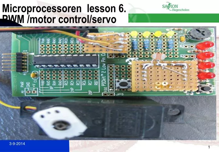
Microprocessoren lesson 6. PWM /motor control/servo. Example applications PWM. PWM. Power control: Motor control Light Dimmer Servo control. PWM 2. PWM 3. PWM 4 Equations. Summary registers pwm.

E N D
Exampleapplications PWM PWM • Power control: • Motor control • Light Dimmer • Servo control
1. Configure the PWM pins P1A and P1B (andP1C and P1D, if used) as inputs by setting thecorresponding TRISC bits. 2. Set the PWM period by loading the PR2 register. 3. Configure the ECCP module for the desiredPWM mode and configuration by loading theCCP1CON register with the appropriate values: • Select one of the available outputconfigurations and direction with theP1M<1:0> bits. • Select the polarities of the PWM outputsignals with the CCP1M<3:0> bits. 4. Set the PWM duty cycle by loading the CCPR1Lregister and CCP1CON<5:4> bits. 5. For Half-bridge Output mode, set the dead banddelay by loading PWM1CON<6:0> with theappropriate value. 6. If auto-shutdown operation is required, load theECCPAS register: • Select the auto-shutdown sources using theECCPAS<2:0> bits. • Select the shutdown states of the PWMoutput pins using PSSAC<1:0> andPSSBD<1:0>bits. • Set the ECCPASE bit (ECCPAS<7>). • Configure the comparators using theCMCON0 register (Register 8-1). • Configure the comparator inputs as analoginputs. 7. If auto-restart operation is required, set thePRSEN bit (PWM1CON<7>). 8. Configure and start TMR2: • Clear the TMR2 interrupt flag bit by clearingthe TMR2IF bit (PIR1<1>). • Set the TMR2 prescale value by loading theT2CKPS bits (T2CON<1:0>). • Enable Timer2 by setting the TMR2ON bit(T2CON<2>). 9. Enable PWM outputs after a new PWM cyclehas started: • Wait until TMR2 overflows (TMR2IF bit is set). • Enable the CCP1/P1A, P1B, P1C and/or P1Dpin outputs by clearing the respective TRISCBits • Clear the ECCPASE bit (ECCPAS<7>). PWM 5setup
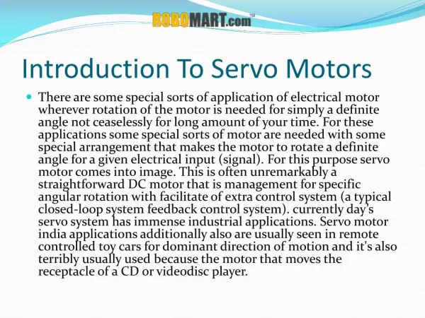
Servo 2 • Controlled by sending a pulse of variable width • Maximum and minimum pulse width to give the angle (1.5 ms neutral position) • Repetition rate (20ms) • The pulse must repeated till angle is reached , after that to stay in that position it has to repeated too • < 1.5ms counterclockwise • > 1.5 ms clockwise • Pulse is generally between 1 and 2 ms • Turn rate: time it takes from one position to another. This can take seconds.
Servo specifications Control System: +Pulse Width Control 1500usec NeutralRequired Pulse: 3-5 Volt Peak to Peak Square WaveOperating Voltage: 4.8-6.0 VoltsOperating Temperature Range: -20 to +60 Degree COperating Speed (4.8V): 0.16sec/60 degrees at no loadOperating Speed (6.0V): 0.13sec/60 degrees at no loadStall Torque (4.8V): 76.37 oz/in. (5.5kg.cm)Stall Torque (6.0V): 94.43 oz/in. (6.8kg.cm)Operating Angle: 45 Deg. one side pulse traveling 400usec360 Modifiable: YesDirection: Clockwise/Pulse Traveling 1500 to 1900usecCurrent Drain (4.8V): 8.8mA/idle and 400mA no load operatingCurrent Drain (6.0V): 9.1mA/idle and 500mA no load operatingDead Band Width: 8usecMotor Type: 3 Pole FerritePotentiometer Drive: Indirect Drive Bearing Type: Dual Ball BearingGear Type: 3 Metal Gears and 1 Resin Metal GearConnector Wire Length: 11.81" (300mm)Dimensions: 1.59" x 0.77"x 1.48" (40.6 x 19.8 x 37.8mm)Weight: 1.94oz. (55.2g)
Assignment 6 Practical lesson 7 Choice 1 or 2 • 1.Write a program which turns over the analogue value of a pot meter into the speed of an engine using PWM. • 2. Write a program which turns over the analogue value of a pot meter into the position of a servo-engine using PWM..