Download
1 / 17
200 likes | 421 Views
A New CO 2 Laser Heating System at GSECARS: A COMPRES Infrastructure Development Project. Alexei Yu. Kuznetsov 1 , Vitali B. Prakapenka 1 , Andrew J. Campbell 2 , Thomas S. Duffy 3 , Guoyin Shen 4 , Dion L. Heinz 1 , Mark L. Rivers 1 , Stephen R. Sutton 1

E N D
A New CO2 Laser Heating System at GSECARS: A COMPRES Infrastructure Development Project Alexei Yu. Kuznetsov1 ,Vitali B. Prakapenka1, Andrew J. Campbell2, Thomas S. Duffy3, Guoyin Shen4, Dion L. Heinz1, Mark L. Rivers1, Stephen R. Sutton1 1University of Chicago, Chicago, Illinois 60637, USA 2University of Maryland, College Park, MD 20742 3Princeton University, Princeton, NJ 08544 4Carnegie Institution of Washington, 9700 South Cass Ave, Argonne, IL 60439
Acknowledge GSECARS stuff: Mark Rivers Steve Sutton Yanbin Wang Vitali Prakapenka Peter Eng Sanjit Ghose Matt Newville Atsushi Kubo Takeyuki Sanehira Nancy Lazarz Mike Jagger Fred Sopron Clayton Pullins Charlie Smith Przemek Dera COMPRES
Synopsis Introduction - Current status of the project and further plans - CO2 laser heating: main goal CO2 laser heating system - Key design considerations - Main characteristics - Key problems - Concept of the setup Conclusion remarks
Introduction Current status of the project 2007-2 installation of the CO2 laser heating system in the ID-D station Next steps 2007-3 commissioning of the system 2008-1 commissioning with local proposals 2008-2 open to general users
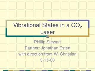
Introduction CO2 laser =10.6 m YAG, YLF, Fiber lasers ~ 1 m Jan L. C. Wijers, Technische Rundschau, Bern TR Transfer nr. 112 1996 F. Kemper et al. Nature 415 (2002), 295 Laboratory Astrophysics Group of the AIU Jena: http://www.astro.uni-jena.de/Laboratory/OCDB/index.html
CO2 laser heating system • Key design consideration • Integrated into existing NIR (~1 m wavelength) laser heating setup • Compact design • Power stability and control • Quick switch between the NIR and CO2 laser heating • IR (~10 m) sample alignment • Monitoring of the heating process (IR, Vis) • Full remote control and user friendly operation • Safety
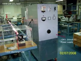
CO2 laser: main characteristics Synrad f201 laser Wavelength 10.2-10.7 m Power output 200 W (CW), 250 W (PWM) Mode quality TEM00, 98% purity Polarization Linear, horizontal Beam diameter 4.5 mm (at laser output) Beam divergence 4.0 mrad
CO2 laser heating system: key problems Power stability and power control Pulsed width modulation command signal waveform Polarizer-Analyzer-Attenuator (Brewster windows)
2 1 2> 1 CO2 laser heating system: key problems Sample alignment is a key issue in a successful HP experiment Imaging in ~ 10 m Problems of using visible wavelength range: 1. Chromatic effect 2. Heating process is visible only when sample is starting to emit the light (T ~1500K)
CO2 laser heating system: key problems Switch between NIR and CO2 laser heating Silver based coating Reflects ~98% of the light at both wavelengths
Beam splitter CO2 laser heating system General scheme
Diffraction at 3 um Magnification 11 No Diffraction Raw Image Magnification 11 Diffraction at 10.6 um Magnification 4 Diffraction at 10.6 um Magnification 11 (b) (a) 300 m 300 m Back illuminated by IR light Heated to 450 oC What do IR images look like? Trade-off between magnification and image quality Simulated by David Koren, II-VI Infrared. Magnified images of the wire
300 m What do IR images look like? Sample in the DAC
Conclusion remarks • The combination of a synchrotron X-ray source with a laser-heated DAC has been providing important results and new discoveries in high pressure mineral physics • Comprehensive laser heating setup is one of the important components defining versatility of high-pressure / high-temperature studies at GSECARS
Temperature measurements Planck’s law Optics correction Emissivity correction Emissivity model - fitting parameters - adjustable parameter