Download

1 / 25
410 likes | 2.54k Views
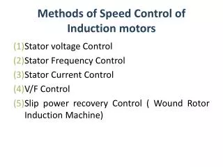
SPEED SYNCHRONISATION OF MULTIPLE MOTORS IN TEXTILE MILLS. Submitted by:. CONTENTS. Introduction Block diagram Power supply PIC Microcontroller BLDC Motor Opto-isolator MOSFET IR LED & Photodiode Keypad LCD Schematic & Working of the project Advantages Applications Future scope

E N D
SPEED SYNCHRONISATION OF MULTIPLE MOTORS IN TEXTILE MILLS Submitted by:
CONTENTS • Introduction • Block diagram • Power supply • PIC Microcontroller • BLDC Motor • Opto-isolator • MOSFET • IR LED & Photodiode • Keypad • LCD • Schematic & Working of the project • Advantages • Applications • Future scope • Conclusion
Project overview • This project describes a message based monitoring tool using the RS232 Rx Tx features of the MC to communicate between 3 PIC MCs. • In this project 3 motors are been synchronized. The required speed is entered with a keypad fed master controller which in turn controls the slave-1 which controls slave-2. IR sensors are used to sense the speed.
Power supply Step down transformer Bridge rectifier Filter Regulator
Contd.. • The 230V AC supply is first stepped down to 12V AC using a step down transformer. • This is then converted to DC using bridge rectifier. • The AC ripples is filtered out by using a capacitor and given to the input pin of voltage regulator 7805. • At output pin of this regulator we get a constant 5V DC which is used for MC and other ICs in this project.
PIC (PIC16F877A) • High-Performance RISC CPU: • Only 35 single-word instructions. • All single-cycle instructions except for program branches, which are two cycle. • Operating speed: DC – 20 MHz clock input DC – 200 ns instruction cycle • Up to 8K x 14 words of Flash Program Memory, Up to 368 x 8 bytes of Data Memory (RAM), Up to 256 x 8 bytes of EEPROM Data Memory. • Pin out compatible to other 28-pin or 40/44-pin, PIC16CXXX and PIC16FXXX microcontrollers.
Special Microcontroller Features: • 100,000 erase/write cycle Enhanced Flash program memory typical. • 1,000,000 erase/write cycle Data EEPROM memory typical. • Data EEPROM Retention > 40 years. • Self-reprogrammable under software control. • In-Circuit Serial Programming™ (ICSP™) via two pins. • Single-supply 5V In-Circuit Serial Programming. • Watchdog Timer (WDT) with its own on-chip RC oscillator for reliable operation. • Programmable code protection. • Power saving Sleep mode. • Selectable oscillator options. • In-Circuit Debug (ICD) via two pins.
Peripheral Features: • Timer0: 8-bit timer/counter with 8-bit prescaler. • Timer1: 16-bit timer/counter with prescaler, can be incremented during Sleep via external crystal/clock. • Timer2: 8-bit timer/counter with 8-bit period register, prescaler and postscaler. • Two Capture, Compare, PWM modules • - Capture is 16-bit, max. resolution is 12.5 ns • - Compare is 16-bit, max. resolution is 200 ns • - PWM max resolution is 10-bit • Synchronous Serial Port (SSP) with SPI™ (Master mode) and I2C™ (Master/Slave). • Universal Synchronous Asynchronous Receiver Transmitter (USART/SCI) with 9-bit address detection. • Parallel Slave Port (PSP) – 8 bits wide with external RD, WR and CS controls (40/44-pin only). • Brown-out detection circuitry for Brown-out Reset (BOR).
BLDC motor • Standard DC motor -- Magnetic field is stationary in stator, rotor poles switch polarity due to commutation to provide constant rotation. • Brushless DC motor -- Magnetic field of rotor is fixed. Magnetic field in stator poles is electronically commutated, provides rotating magnetic field. • Motor contains internal position encoder to provide position feedback to the control system.
Contd.. • Applications - CPU cooling fans - CD/DVD Players - Electric automobiles • Pros (compared to brushed DC) - Higher efficiency - Longer lifespan, low maintenance - Clean, fast, no sparking/issues with brushed contacts • Cons - Higher cost - More complex circuitry and requires a controller.
Opto-isolator • Opto coupler is a 6 pin IC. It is a combination of 1 LED and a transistor. • Pin 6 of transistor is not generally used and when light falls on the Base-Emitter junction then it switches and pin5 goes to zero. • If input of the diode is zero and other end of diode is GND then the output is one. • When logic zero is given as input then the light doesn’t fall on transistor so it doesn’t conduct which gives logic zero as output. • When logic 1 is given as input then light falls on transistor so that it conducts, that makes transistor switched ON and it forms short circuit this makes the output is logic zero as collector of transistor is connected to ground.
MOSFET • The MOSFET (Metal Oxide Semiconductor Field Effect Transistor) is a Voltage controlled device. • This means that a voltage at the gate control the current flows from the drain to the source. • There are three terminals: Gate - connected to the input device. • Drain - connected to the positive, since electrons drain away to the positive. Source - the source of the electrons
Contd.. • USES OF MOSFETS High power devices like motors and light bulbs give a large current output for a very tiny current input. • So a MOSFET can act as the interface between an integrated circuit that can give only a tiny current, and the motor that takes a big current. • In complimentary pairs they are used in hi-fi power amplifiers. • They produce less distortion as they are more linear than bipolar transistors. • Integrated circuits, as they can be made very compact.
IR LED • Here the IR transmitter is like a normal LED but transmits the IR signals. • These are infrared LEDs; the light output is not visible by our eyes. They can be used as replacement LEDs for remote controls, night vision for camcorders, invisible beam sensors, etc.
Photodiode • Here the photodiode is like a normal LED but receives the IR signals. • A photodiode is a type of photo detector capable of converting light into either current or voltage, depending upon the mode of operation.
Keypad • A keypad is a set of buttons arranged in a block or "pad" which usually bear digits, symbols and usually a complete set of alphabetical letters. If it mostly contains numbers then it can also be called a numeric keypad. • In order to detect which key is pressed from the matrix, the row lines are to be made low one by one and read the columns. Assume that if Row1 is made low, then read the columns. • If any of the key in row1 is pressed then correspondingly the column 1will give low that is if second key is pressed in Row1, then column2 will give low.
Liquid Crystal Display-LCD • Most common LCDs connected to the microcontrollers are 16x2 and 20x2 displays. • This means 16 characters per line by 2 lines and 20 characters per line by 2 lines, respectively. • The standard is referred to as HD44780U, which refers to the controller chip which receives data from an external source (and communicates directly with the LCD.
Contd.. • If an 8-bit data bus is used the LCD will require 11 data lines(3 control lines plus the 8 lines for the data bus) • The three control lines are referred to as EN, RS, and RW • EN=Enable (used to tell the LCD that you are sending it data) • RS=Register Select. When RS=0; data is treated as a command & When RS=1; data being sent is text data. • R/W=Read/Write . When RW=0; the data written to the LCD & When RW=1; the data reading to the LCD.
Working of project • The speed of the motor is sensed by an IR pair and is displayed on LCD and is also fed to the MC. • The required speed is entered using a keypad which is interfaced with MC. • The motor is interfaced to the MC through a opto-coupler & a MOSFET which drives the motor. • PWM pulses are generated from MC according to the entered speed and the motor is adjusted to that speed and maintained at that speed.