Download
1 / 23
260 likes | 571 Views
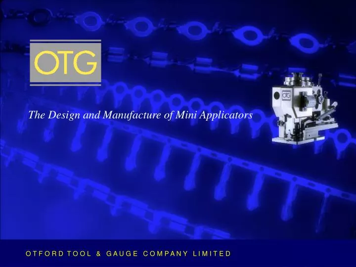
The Design and Manufacture of Mini Applicators. O T F O R D T O O L & G A U G E C O M P A N Y L I M I T E D. Any Terminal Manufacturer Any Terminal Standard Applicator Range Special Applicators. O T F O R D T O O L & G A U G E C O M P A N Y L I M I T E D.

E N D
The Design and Manufacture of Mini Applicators O T F O R D T O O L & G A U G E C O M P A N Y L I M I T E D
Any Terminal Manufacturer • Any Terminal • Standard Applicator Range • Special Applicators O T F O R D T O O L & G A U G E C O M P A N Y L I M I T E D
The Standard Applicator Range O T F O R D T O O L & G A U G E C O M P A N Y L I M I T E D
The Standard Applicator Range For wire CSA up to 20sq mm • Left hand side feed • Right hand side feed • End feed • Pneumatic feed
Mini Applicator Specifications • Industry standard height 135.78mm • Industry standard 3 pointpress location • Standard “off the shelf”tooling range • Continuously adjustablecrimp height • Rigid modular construction using high tensile materials
Pneumatic Feed • Left hand S.F • Right hand S.F • End feed
Press opening height - max 135.78mm min 132.5mm Press opening stroke - max 40mm min 28mm Left hand and right hand SF – max 28mm End feed – max 25mm Pneumatic feed applicators are designed to apply terminals with afeed pitch longer than above Mini Applicator Specifications Terminal feed stroke
Standard Tooling • Comprehensive range of standardset sizes crimp widths andmaterial thickness • Computer optimised design forgreater accuracy of tooling selection • High quality alloy steels, vacuum hardened and hard chrome plated • Full material and hardening trace ability • High stock levels of standard components • Fast delivery of standard applicators and tooling spares
Design & Development Facilities • Highly experienced design team • Comprehensive data base of known terminals and characteristics • State of the art 3D computer modelling software • Continuous development of new products • Database of 11,000 designs • Repeat designs can be in production within 24 hours of receipt of order
Prototype Facilities • Applicators for terminals not on the OTG design database are firstly prototyped ensuring accuracy of the database for production • Development and prototyping with a dedicated staff is a continuous process • 3D computer modelling enables development time to be reduced
Special Purpose Applicators • Applicators for terminals and applications which fall outside the OTG standard applicator and tooling range • Up to 36sq mm wire • Non standard press opening height • Special feed/loading requirements • As press tools for other processes
Production Capability • Up to date CNC machine tools • Traditional tool making skills • Standardisation brings high efficiency and flexibility
Tool Making • MRPII manufacture of parts • Manufacturing process trace ability • Week number scheduling
Longer Tooling Life • Crimp tooling profiles are form ground giving superior finish and accuracy • Ground profile is finished with a diamond lapping process • Hard chrome plated
Engraving • All components engravedwith part number • Standard tooling spares • The part number describesthe part
Inspection • All components fully inspected prior to stocking • All items and material specfully traceable • All completed applicators inspected prior to despatch • Documentation – certificateof incorporation issued with every applicator
Stock Control • Comprehensive stock of over 12,000 part numbers • Standard components in stock for immediate delivery • Computer controlledstock system • Experienced purchasing and stock control personnel
Applicator Production Build & Test • Modular build system gives speed and flexibility of assembly • Standard components • OTG design and build technology gives a proven result • 200-250 units, 4-6 weeks delivery* • 1-10 units, 2-4 weeks delivery* * From receipt of order, terminals,wire samples and specifications
Capability Testing • All OTG applicators under go capability tests upon completion as part of the final inspection process • Full capability test results and documentation are available at additional costs • OTG provides a proven and tested crimp form • OTG supplies a result
Technical Support The OTG Technical Support Team is available to answer and advise on any technical aspect relating to crimping quality. Our extensive experience enables us to offer:- • Dedicated technical Hotline. • Hands on technical support U.K and World-wide. • Operator training on site at any location.
Sales & Export Support • Dedicated spare parts department • Hotline for emergency spares • Support offices in Portugaland the Philippines
PRESS TOOLS MOULDS FOR PLASTICS JIGS AND FIXTURES SPECIAL PURPOSE EQUIPMENT