Download
1 / 59
610 likes | 646 Views
Chapter 32 Light: Reflection and Refraction. Units of Chapter 32. The Ray Model of Light Reflection; Image Formation by a Plane Mirror Formation of Images by Spherical Mirrors Index of Refraction Refraction: Snell’s Law. Units of Chapter 32. Visible Spectrum and Dispersion

E N D
Units of Chapter 32 • The Ray Model of Light • Reflection; Image Formation by a Plane Mirror • Formation of Images by Spherical Mirrors • Index of Refraction • Refraction: Snell’s Law
Units of Chapter 32 • Visible Spectrum and Dispersion • Total Internal Reflection; Fiber Optics • Refraction at a Spherical Surface
32-1 The Ray Model of Light Light very often travels in straight lines. We represent light using rays, which are straight lines emanating from an object. This is an idealization, but is very useful for geometric optics.
32-2 Reflection; Image Formation by a Plane Mirror Law of reflection: the angle of reflection (that the ray makes with the normal to a surface) equals the angle of incidence.
32-2 Reflection; Image Formation by a Plane Mirror When light reflects from a rough surface, the law of reflection still holds, but the angle of incidence varies. This is called diffuse reflection.
32-2 Reflection; Image Formation by a Plane Mirror With diffuse reflection, your eye sees reflected light at all angles. With specular reflection (from a mirror), your eye must be in the correct position.
32-2 Reflection; Image Formation by a Plane Mirror Example 32-1: Reflection from flat mirrors. Two flat mirrors are perpendicular to each other. An incoming beam of light makes an angle of 15° with the first mirror as shown. What angle will the outgoing beam make with the second mirror?
32-2 Reflection; Image Formation by a Plane Mirror What you see when you look into a plane (flat) mirror is an image, which appears to be behind the mirror.
32-2 Reflection; Image Formation by a Plane Mirror This is called a virtual image, as the light does not go through it. The distance of the image from the mirror is equal to the distance of the object from the mirror.
32-2 Reflection; Image Formation by a Plane Mirror Example 32-2: How tall must a full-length mirror be? A woman 1.60 m tall stands in front of a vertical plane mirror. What is the minimum height of the mirror, and how close must its lower edge be to the floor, if she is to be able to see her whole body? Assume her eyes are 10 cm below the top of her head.
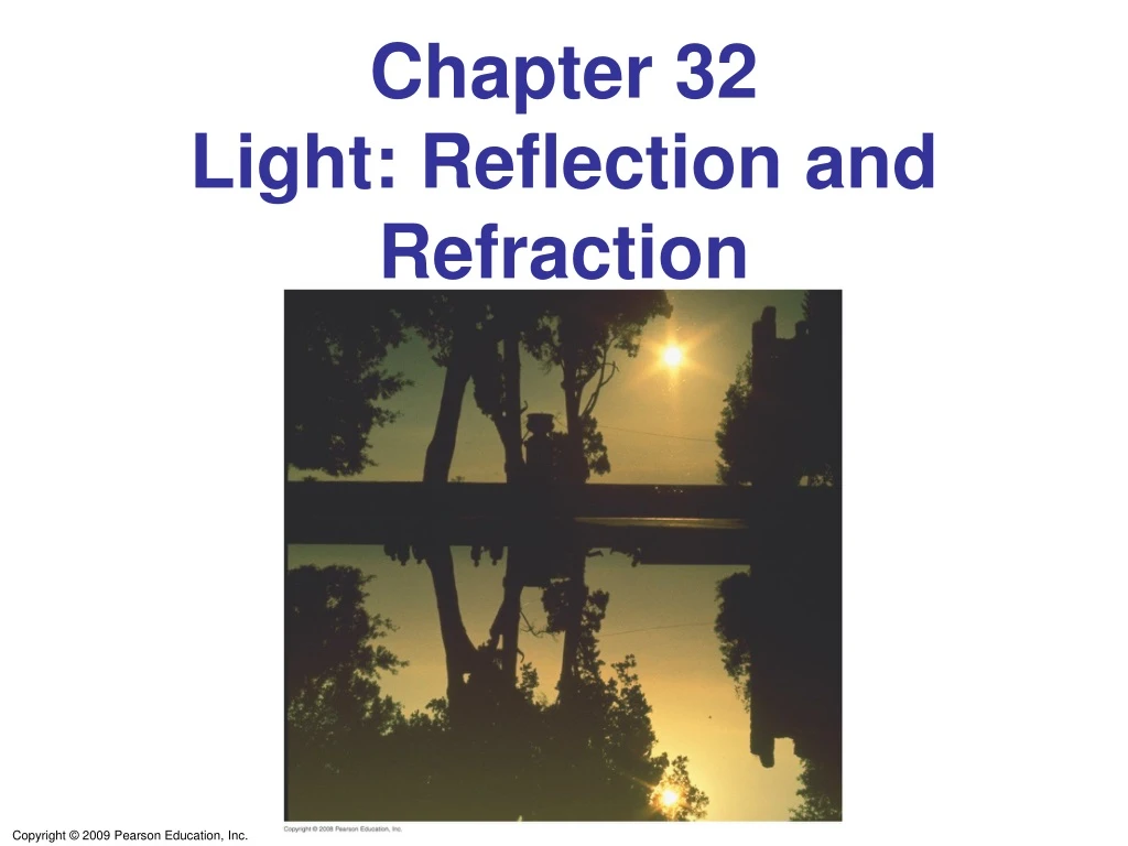
32-2 Reflection; Image Formation by a Plane Mirror Conceptual Example 32-3: Is the photo upside down? Close examination of the photograph on the first page of this Chapter reveals that in the top portion, the image of the Sun is seen clearly, whereas in the lower portion, the image of the Sun is partially blocked by the tree branches. Show why the reflection is not the same as the real scene by drawing a sketch of this situation, showing the Sun, the camera, the branch, and two rays going from the Sun to the camera (one direct and one reflected). Is the photograph right side up?
32-3 Formation of Images by Spherical Mirrors Spherical mirrors are shaped like sections of a sphere, and may be reflective on either the inside (concave) or outside (convex).
32-3 Formation of Images by Spherical Mirrors Rays coming from a faraway object are effectively parallel.
32-3 Formation of Images by Spherical Mirrors Parallel rays striking a spherical mirror do not all converge at exactly the same place if the curvature of the mirror is large; this is called spherical aberration.
32-3 Formation of Images by Spherical Mirrors If the curvature is small, the focus is much more precise; the focal point is where the rays converge.
32-3 Formation of Images by Spherical Mirrors Using geometry, we find that the focal length is half the radius of curvature: Spherical aberration can be avoided by using a parabolic reflector; these are more difficult and expensive to make, and so are used only when necessary, such as in research telescopes.
32-3 Formation of Images by Spherical Mirrors • We use ray diagrams to determine where an image will be. For mirrors, we use three key rays, all of which begin on the object: • A ray parallel to the axis; after reflection it passes through the focal point. • A ray through the focal point; after reflection it is parallel to the axis. • A ray perpendicular to the mirror; it reflects back on itself.
32-3 Formation of Images by Spherical Mirrors The intersection of these three rays gives the position of the image of that point on the object. To get a full image, we can do the same with other points (two points suffice for may purposes).
32-3 Formation of Images by Spherical Mirrors Geometrically, we can derive an equation that relates the object distance, image distance, and focal length of the mirror:
32-3 Formation of Images by Spherical Mirrors We can also find the magnification (ratio of image height to object height): The negative sign indicates that the image is inverted. This object is between the center of curvature and the focal point, and its image is larger, inverted, and real.
32-3 Formation of Images by Spherical Mirrors Example 32-4: Image in a concave mirror. A 1.50-cm-high diamond ring is placed 20.0 cm from a concave mirror with radius of curvature 30.0 cm. Determine (a) the position of the image, and (b) its size.
32-3 Formation of Images by Spherical Mirrors Conceptual Example 32-5: Reversible rays. If the object in this figure is placed where the image is, where will the new image be? Figure 32-16 goes here.
32-3 Formation of Images by Spherical Mirrors If an object is outside the center of curvature of a concave mirror, its image will be inverted, smaller, and real.
32-3 Formation of Images by Spherical Mirrors Example 32-6: Object closer to concave mirror. A 1.00-cm-high object is placed 10.0 cm from a concave mirror whose radius of curvature is 30.0 cm. (a) Draw a ray diagram to locate (approximately) the position of the image. (b) Determine the position of the image and the magnification analytically.
32-3 Formation of Images by Spherical Mirrors For a convex mirror, the image is always virtual, upright, and smaller.
32-3 Formation of Images by Spherical Mirrors • Problem Solving: Spherical Mirrors • Draw a ray diagram; the image is where the rays intersect. • Apply the mirror and magnification equations. • Sign conventions: if the object, image, or focal point is on the reflective side of the mirror, its distance is positive, and negative otherwise. Magnification is positive if image is upright, negative otherwise. • Check that your solution agrees with the ray diagram.
ConcepTest 32.1 Reflection 1) the Moon is very large 2) atmospheric conditions are just right 3) the ocean is calm 4) the ocean is wavy 5) motion of the Moon When watching the Moon over the ocean, you often see a long streak of light on the surface of the water. This occurs because:
ConcepTest 32.1 Reflection 1) the Moon is very large 2) atmospheric conditions are just right 3) the ocean is calm 4) the ocean is wavy 5) motion of the Moon When watching the Moon over the ocean, you often see a long streak of light on the surface of the water. This occurs because: When the water surface changes, the angle of incidence also changes. Thus, different spots on the water can reflect the Mooninto your eyes at different times. Follow-up: Where else does this occur?
mirror 3 O 1 2 S 4 ConcepTest 32.2a Mirror I An observer at point O is facing a mirror and observes a light source S. Where does the observer perceive the mirror image of the source to be located?
mirror 3 O 1 2 S 4 ConcepTest 32.2a Mirror I An observer at point O is facing a mirror and observes a light source S. Where does the observer perceive the mirror image of the source to be located? Trace the light rays from the object to the mirror to the eye. Since the brain assumes that light travels in a straight line, simply extend the rays back behind the mirror to locate the image. Follow-up: What happens when the observer starts moving toward the mirror?
32-4 Index of Refraction In general, light slows somewhat when traveling through a medium. The index of refraction of the medium is the ratio of the speed of light in vacuum to the speed of light in the medium:
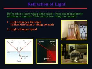
32-5 Refraction: Snell’s Law Light changes direction when crossing a boundary from one medium to another. This is called refraction, and the angle the outgoing ray makes with the normal is called the angle of refraction.
32-5 Refraction: Snell’s Law Refraction is what makes objects half-submerged in water look odd.
32-5 Refraction: Snell’s Law The angle of refraction depends on the indices of refraction, and is given by Snell’s law:
32-5 Refraction: Snell’s Law Example 32-8: Refraction through flat glass. Light traveling in air strikes a flat piece of uniformly thick glass at an incident angle of 60°, as shown. If the index of refraction of the glass is 1.50, (a) what is the angle of refraction θA in the glass; (b) what is the angle θB at which the ray emerges from the glass?
32-5 Refraction: Snell’s Law Example 32-9: Apparent depth of a pool. A swimmer has dropped her goggles to the bottom of a pool at the shallow end, marked as 1.0 m deep. But the goggles don’t look that deep. Why? How deep do the goggles appear to be when you look straight down into the water?
air air 1 ConcepTest 32.4aRefraction I Parallel light rays cross interfaces from air into two different media, 1 and 2, as shown in the figures below. In which of the media is the light traveling faster? 1) medium 1 2) medium 2 3) both the same 2
air air 1 ConcepTest 32.4aRefraction I Parallel light rays cross interfaces from air into two different media, 1 and 2, as shown in the figures below. In which of the media is the light traveling faster? 1) medium 1 2) medium 2 3) both the same The greater the difference in the speed of light between the two media, the greater the bending of the light rays. 2 Follow-up:How does the speed in air compare to that in #1 or #2?
32-6 Visible Spectrum and Dispersion The visible spectrum contains the full range of wavelengths of light that are visible to the human eye.
32-6 Visible Spectrum and Dispersion The index of refraction of many transparent materials, such as glass and water, varies slightly with wavelength. This is how prisms and water droplets create rainbows from sunlight.
32-6 Visible Spectrum and Dispersion This spreading of light into the full spectrum is called dispersion.
32-6 Visible Spectrum and Dispersion Conceptual Example 32-10: Observed color of light under water. We said that color depends on wavelength. For example, for an object emitting 650 nm light in air, we see red. But this is true only in air. If we observe this same object when under water, it still looks red. But the wavelength in water λn is 650 nm/1.33 = 489 nm. Light with wavelength 489 nm would appear blue in air. Can you explain why the light appears red rather than blue when observed under water?
32-7 Total Internal Reflection; Fiber Optics If light passes into a medium with a smaller index of refraction, the angle of refraction is larger. There is an angle of incidence for which the angle of refraction will be 90°; this is called the critical angle:
32-7 Total Internal Reflection; Fiber Optics If the angle of incidence is larger than this, no transmission occurs. This is called total internal reflection.
32-7 Total Internal Reflection; Fiber Optics Conceptual Example 32-11: View up from under water. Describe what a person would see who looked up at the world from beneath the perfectly smooth surface of a lake or swimming pool.
32-7 Total Internal Reflection; Fiber Optics Binoculars often use total internal reflection; this gives true 100% reflection, which even the best mirror cannot do.
32-7 Total Internal Reflection; Fiber Optics Optical fibers also depend on total internal reflection; they are therefore able to transmit light signals with very small losses.
32-8 Refraction at a Spherical Surface Rays from a single point will be focused by a convex spherical interface with a medium of larger index of refraction to a single point, as long as the angles are not too large.