Download
1 / 18
191 likes | 356 Views
Current and voltage on a transmission line : Look for V=ZI. Alan Murray. Also … can a “real” Line with R>0, G>0 (slightly lossy ) be truly distortionless ?. It turns out that it can, provided that

E N D
Current and voltage on a transmission line:Look for V=ZI Alan Murray
Also … can a “real” Line with R>0, G>0 (slightly lossy) be truly distortionless? • It turns out that it can, provided that • This is known as the Heaviside Condition and allows a line to be designed to have zero distortion, even with R>0, G>0 Oliver Heaviside (1850 - 1925) - English physicist and electrical engineer Also known for predicting the "Heaviside Layer" in the atmosphere
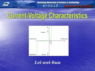
Current on a transmission line • So far we have mainly considered the voltage on a transmission line • The instantaneous voltage at any given point is the SUM of the forward and backward wave voltages. • The current has (almost) the same form • I=V/R, but I+ and I- in opposite directions I+← I-→
Current on a transmission line … more non-examinable maths! Telegrapher’s Equations Look for V=ZI, I=V/Z From last lecture
Current on a transmission line … more non-examinable maths! The characteristic impedance of the line
Sanity check – Characteristic Impedance of Lossless Line? In the lossless case, Zo is purely REAL, i.e. resistive
Characteristic Impedanceof a Slightly Lossy Line Series expansions “small” x “small” = “very small”!
Characteristic Impedanceof a Slightly Lossy Line This is complex , but if () = 0 … i.e. So although the line has losses, its characteristic impedance is the same as that of a lossless line and no dispersion → distortion occurs. This is known as the Heaviside condition for a distortionless line.
Characteristic Impedance – Some General Points • The characteristic impedance relates: • the forward voltage wave V+ to the forward current wave I+ • or • the backward voltage wave V- to the backward current wave I- • It does not link the total current and voltage (unless V-=I-=0) X L J
NB Z0 is not the impedance measured by connecting the line to an impedance meter • This would give the open-circuitimpedance, ZOC. • We will see laterthatZ0 = (ZOCZSC)½ • where ZSC is theshort-circuitimpedance.
Example 4.1 - Characteristic impedance of a parallel-wire line. • Calculate the characteristic impedance of a lossless, air-spaced, two-wire transmission line for which the wire radius is 0.5 mm and the spacing is 5mm. “it can be shown that …” 5mm 0.5mm
Example 4.1 - Characteristic impedance of a parallel-wire line. 5mm 0.5mm
Example 4.2 Characteristic impedance of a coaxial line. • A coaxial, lossless transmission line with an inner conductor of diameter 2mm and internal diameter for the exterior conductor of 7.5 mm is filled with polythene dielectric (εr = 2.56, µr = 1). Calculate the characteristic impedance of the line. b=3.75mm a=1mm
Example 4.2 Characteristic impedance of a coaxial line. “it can be shown that …” b=3.75mm a=1mm
Reflections on Transmission Lines • Voltage and current waves on transmission lines can be reflected. • They are reflected by discontinuities • e.g. a load or a changeover from one type of line to another. • A transmission line with discontinuities will also have backward (or reflected) waves
Reflections on Transmission Lines • The total voltage and current on the line are thus VT = V++V- and IT = I+–I- • The impedance seen by the source will depend on the magnitude and phase of these reflections. • VT /IT= ZIN • Power delivered to the end of the transmission line is reduced by reflections. • When there are no reflections the power delivered to the end of the line, and thus the load, is maximised
Infinitely Long Transmission Lines • There are no discontinuities and so no reflections • the total voltage and total current at any point on theline (including the input end)will be given by: • The line just “looks like” a load Z0 I I = Zo V V Infinite line with characteristic impedance Zo
Preventing Reflections and Power Loss • Match impedances!