Download
1 / 16
160 likes | 377 Views
Register-Transfer Level (RTL) Design. Recall Chapter 2: Combinational Logic Design First step: Capture behavior (using equation or truth table) Remaining steps: Convert to circuit Chapter 3: Sequential Logic Design First step: Capture behavior (using FSM) Remaining steps: Convert to circuit

E N D
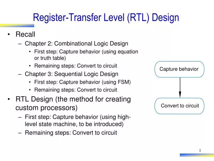
Register-Transfer Level (RTL) Design • Recall • Chapter 2: Combinational Logic Design • First step: Capture behavior (using equation or truth table) • Remaining steps: Convert to circuit • Chapter 3: Sequential Logic Design • First step: Capture behavior (using FSM) • Remaining steps: Convert to circuit • RTL Design (the method for creating custom processors) • First step: Capture behavior (using high-level state machine, to be introduced) • Remaining steps: Convert to circuit Capture behavior Convert to circuit
T (in seconds) laser D Object of interest sensor 2D = T sec * 3*108 m/sec Step 1: Laser-Based Distance Measurer • Example of how to create a high-level state machine to describe desired processor behavior • Laser-based distance measurement – pulse laser, measure time T to sense reflection • Laser light travels at speed of light, 3*108 m/sec • Distance is thus D = T sec * 3*108 m/sec / 2
B L from button to laser Laser-based distance 16 D S measurer to display from sensor Step 1: Laser-Based Distance Measurer • Inputs/outputs • B: bit input, from button to begin measurement • L: bit output, activates laser • S: bit input, senses laser reflection • D: 16-bit output, displays computed distance T (in seconds) laser sensor
B L from button to laser Laser- based distance 16 D S measurer to display from sensor S0 ? L = 0 (laser off) D = 0 (distance = 0) Step 1: Laser-Based Distance Measurer • Step 1: Create high-level state machine • Begin by declaring inputs and outputs • Create initial state, name it S0 • Initialize laser to off (L=0) • Initialize displayed distance to 0 (D=0) Inputs: B , S (1 bit each) Outputs: L (bit), D (16 bits) a
B L from button to laser Laser- based distance B’ (button not pressed) 16 D S measurer to display from sensor ? S1 B (button pressed) Step 1: Laser-Based Distance Measurer Inputs: B, S (1 bit each) • Add another state, call S1, that waits for a button press • B’ – stay in S1, keep waiting • B – go to a new state S2 Outputs: L (bit), D (16 bits) a S0 S0 L = 0 D = 0 Q: What should S2 do? A: Turn on the laser a
B L from button to laser Laser- based distance 16 D S measurer to display from sensor S3 L = 0 (laser off) Step 1: Laser-Based Distance Measurer Inputs: B, S (1 bit each) • Add a state S2 that turns on the laser (L=1) • Then turn off laser (L=0) in a state S3 Outputs: L (bit), D (16 bits) B’ S0 S1 S2 B a L = 0 L = 1 D = 0 (laser on) Q: What do next? A: Start timer, wait to sense reflection a
B L f r om but t on S’ (no reflection) t o laser Lase r -based distan c e 16 D S measu r er S (reflection) t o displ a y f r om sensor ? Dctr = 0 (reset cycle Dctr = Dctr + 1 count) (count cycles) Step 1: Laser-Based Distance Measurer Inputs: B, S (1 bit each) Outputs: L (bit), D (16 bits) • Stay in S3 until sense reflection (S) • To measure time, count cycles for which we are in S3 • To count, declare local register Dctr • Increment Dctr each cycle in S3 • Initialize Dctr to 0 in S1. S2 would have been O.K. too Local Registers: Dctr (16 bits) B’ S0 S1 S2 S3 B L = 0 L = 1 L = 0 a D = 0
B L f r om but t on t o laser Lase r -based distan c e 16 D S measu r er t o displ a y f r om sensor S4 D = Dctr / 2 (calculate D) Step 1: Laser-Based Distance Measurer • Once reflection detected (S), go to new state S4 • Calculate distance • Assuming clock frequency is 3x10⁸, Dctr holds number of meters, so D=Dctr/2 • After S4, go back to S1 to wait for button again Inputs: B, S (1 bit each) Outputs: L (bit), D (16 bits) Local Registers: Dctr (16 bits) S’ B’ a S0 S1 S2 S3 B S L = 0 Dctr = 0 L = 1 L=0 D = 0 Dctr = Dctr + 1
Step 2: Create a Datapath • Datapath must • Implement data storage • Implement data computations • Look at high-level state machine, do three substeps • (a) Make data inputs/outputs be datapath inputs/outputs • (b) Instantiate declared registers into the datapath (also instantiate a register for each data output) • (c) Examine every state and transition, and instantiate datapath components and connections to implement any data computations Instantiate: to introduce a new component into a design.
Local Registers: Dctr (16 bits) ‘ ‘ B S S4 S0 S1 S2 S3 B S L = 0 Dctr = 0 L = 1 L=0 D = Dctr / 2 D = 0 Dctr = Dctr + 1 (calculate D) D r eg_clr D r eg_ld clear clear I D c tr_clr D c t r : 16-bit D r eg: 16-bit c ou n t D c tr_c n t load u p - c ou n t er r e g is t er Q Q 16 D Step 2: Laser-Based Distance Measurer (a) Make data inputs/outputs be datapath inputs/outputs (b) Instantiate declared registers into the datapath (also instantiate a register for each data output) (c) Examine every state and transition, and instantiate datapath components and connections to implement any data computations Inputs: B, S (1 bit each) Outputs: L (bit), D (16 bits) a D a tap a th
Local Registers: Dctr (16 bits) ‘ ‘ B S S4 S0 S1 S2 S3 B S L = 0 Dctr = 0 L = 1 L=0 D = Dctr / 2 D = 0 Dctr = Dctr + 1 (calculate D) >>1 16 16 Step 2: Laser-Based Distance Measurer (c) (continued) Examine every state and transition, and instantiate datapath components and connections to implement any data computations Inputs: B, S (1 bit each) Outputs: L (bit), D (16 bits) a D a tap a th D r eg_clr D r eg_ld clear clear I D c tr_clr D c t r : 16-bit D r eg: 16-bit c ou n t D c tr_c n t load u p - c ou n t er r e g is t er Q Q 16 D
L B to laser from button Controller from sensor S Dreg_clr Dreg_ld Dctr_clr Datapath Dctr_cnt D to display >>1 16 300 M H z Clock 16 Datapath Dreg_clr Dreg_ld 16 Dctr_clr clear clear I Dctr: 16-bit Dreg: 16-bit Dctr_cnt count load up-counter register Q Q 16 D Step 3: Connecting the Datapath to a Controller • Laser-based distance measurer example • Easy – just connect all control signals between controller and datapath
Inputs: B, S (1 bit each) Outputs: L (bit), D (16 bits) L B Local Registers: Dctr (16 bits) t o laser f r om but t on C o n t r oller r om sensor f S D r eg_clr B’ S’ D r eg_ld D c tr_clr D a tap a th S0 S1 S2 S3 S4 B S D c tr_c n t L = 0 Dctr = 0 L = 1 L=0 D = Dctr / 2 D D = 0 Dctr = Dctr + 1 (calculate D) t o displ a y 16 300 M H z Clock Inputs: B, S Outputs: L, Dreg_clr, Dreg_ld, Dctr_clr, Dctr_cnt B’ S’ B S S0 S1 S2 S3 S4 L = 0 L = 0 L = 1 L = 0 L = 0 Step 4: Deriving the Controller’s FSM • FSM has same structure as high-level state machine • Inputs/outputs all bits now • Replace data operations by bit operations using datapath a Dreg_clr = 1 Dreg_ld = 0 Dctr_clr = 0 Dctr_cnt = 0 (laser off) (clear D reg) Dreg_clr = 0 Dreg_ld = 0 Dctr_clr = 1 Dctr_cnt = 0 (clear count) Dreg_clr = 0 Dreg_ld = 0 Dctr_clr = 0 Dctr_cnt = 0 (laser on) Dreg_clr = 0 Dreg_ld = 0 Dctr_clr = 0 Dctr_cnt = 1 (laser off) (count up) Dreg_clr = 0 Dreg_ld = 1 Dctr_clr = 0 Dctr_cnt = 0 (load D reg with Dctr/2) (stop counting)
Inputs: B, S Outputs: L, Dreg_clr, Dreg_ld, Dctr_clr, Dctr_cnt B’ S’ B’ S’ B S S0 S1 S2 S3 S4 B S S0 S1 S2 S3 S4 L = 0 L = 0 L = 1 L = 0 L = 0 Dreg_clr = 1 Dreg_ld = 0 Dctr_clr = 0 Dctr_cnt = 0 (laser off) (clear D reg) Dreg_clr = 0 Dreg_ld = 0 Dctr_clr = 1 Dctr_cnt = 0 (clear count) Dreg_clr = 0 Dreg_ld = 0 Dctr_clr = 0 Dctr_cnt = 0 (laser on) Dreg_clr = 0 Dreg_ld = 0 Dctr_clr = 0 Dctr_cnt = 1 (laser off) (count up) Dreg_clr = 0 Dreg_ld = 1 Dctr_clr = 0 Dctr_cnt = 0 (load D reg with Dctr/2) (stop counting) L = 0 Dctr_clr = 1 (clear count) L = 1 L = 0 Dreg_ld = 1 Dctr_cnt = 0 (load D reg with Dctr/2) (stop counting) Dreg_clr = 1 (laser off) (clear D reg) (laser on) Dctr_cnt = 1 (laser off) (count up) Step 4: Deriving the Controller’s FSM • Using shorthand of outputs not assigned implicitly assigned 0 a
Datapath L B to laser from button from sensor S Dreg_clr Controller Dreg_clr Dreg_ld Datapath Dctr_clr clear clear I Dctr: 16-bit Dreg: 16-bit Dctr_cnt count load up-counter D register to display Q Q 300 MHz Clock 16 16 D Inputs: B, S Outputs: L, Dreg_clr, Dreg_ld, Dctr_clr, Dctr_cnt >>1 16 B’ S’ B S S0 S1 S2 S3 S4 16 L = 0 Dctr_clr = 1 (clear count) L = 1 L = 0 Dreg_ld = 1 Dctr_cnt = 0 (load D reg with Dctr/2) (stop counting) Dreg_clr = 1 (laser off) (clear D reg) (laser on) Dctr_cnt = 1 (laser off) (count up) Step 4 • Implement FSM as state register and logic (Ch3) to complete the design Dreg_ld Dctr_clr Dctr_cnt