Download
1 / 48
550 likes | 1.62k Views
New Materials for Semiconductor Radiation Detectors. P.J. Sellin Centre for Nuclear and Radiation Physics Department of Physics University of Surrey Guildford, UK. Introduction. A review of recent developments in semiconductor detector materials and technology for X-ray and gamma imaging:

E N D
New Materials for Semiconductor Radiation Detectors • P.J. Sellin • Centre for Nuclear and Radiation Physics • Department of Physics • University of Surrey • Guildford, UK
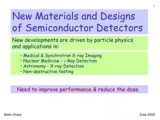
Introduction • A review of recent developments in semiconductor detector materials and technology for X-ray and gamma imaging: • Commercially available or near-market materials: • status of CdZnTe/CdTe • summary of best spectroscopic results from other materials • INTEGRAL/SWIFT – imaging detectors in space • New developments in large-area thick film materials: • polycrystalline and epitaxial CdZnTe/CdTe thick films • Heavy element (Z80) thick films (Hg, Tl, Pb, Bi) • Future materials – latest results from promising new detector materials: • synthetic single-crystal diamond • boron-based semiconductors for neutron detection • Conclusion
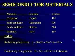
Commercially available or near-market materials • Commercially available material continues to be predominately CdZnTe, plus CdTe and GaAs. • II-VI materials CdTe and CdZnTe cover a suitable range of band gaps: 1.44 eV (CdTe), 1.57 eV (CdZnTe, 10% Zn), 1.64 eV (CdZnTe, 20% Zn) • Resistivity of CdZnTe is higher than CdTe lower dark current, higher spectroscopic resolution • Poor hole transport requires electron-sensitive detector geometries
Commercial suppliers of CdTe/CdZnTe • eV Products continues to be the lead supplier of CdZnTe, grown using various Bridgman techniques: • High Pressure Bridgman (HPB): 1992 • High Pressure Gradient Freeze (HPGF): 1998 • High Pressure Electro-Dynamic Gradient (HP-EDG): 2000 • Electronic heating control, stationary crucible/heater • Reduced thermal stress, less cracking, better single crystal material
CdZnTe ingots grown by HP-EDG • Latest published results from eV Products show 10kg crystals, 140mm (5.5 inch) diameter: • No cracking • Large-grain polycrystalline, with improved single-crystal yield • Reduced concentration of twins • Secondary grain nucleation on crucible walls • IR microscopy used to assess Te inclusions, formed from Te-rich melt: • Mainly triangular or polyhedron shape • Often located along grain boundaries and • Te inclusions act as trapping sites, over a large range C. Szeles et al, J. Electronic Materials, 33 (2004) 742-751
Te inclusions in HP-EDG CdZnTe C. Szeles et al, J. Electronic Materials, 33 (2004) 742-751
Charge transport performance in CdZnTe • Carrier drift length l defines the induced charge Q, and hence the spectroscopic performance of the detector: • For electrons: • The mobility-lifetime product mt is often used as a measure of charge transport quality: HP-EDG material gives mte ~5x10⁻³ cm2/V – some of the best values available with Te inclusions • HP-EDG material shows some non-uniformity of response due to Te inclusion density without Te inclusions C. Szeles et al, J. Electronic Materials, 33 (2004) 742-751
Ion beam mt maps of CdZnTe and CdTe CdZnTe Map of electron mt in CdZnTe shows mte ~ 1x10⁻⁴ cm2/V Highly uniform, no evidence of defects in ‘single crystal’ material Increased mt at right edge due to beam scanning CdTe CdTe electron mt map shows mte ~ 5x10⁻³ cm2/V Pixel detector shows problems with contact delamination in lower quadrants A. Davies, P.J. Sellin et al, IEEE Trans Nucl Sci, in press
CZT grown by Modified Vertical Bridgman – Yinnel Tech • Modified Vertical Bridgman (MVD) CZT has been produced by Yinnel Tech • wafers of large single-crystal areas are claimed, with excellent charge transport • High resistivity r=3x10¹¹Wcm, and mte=1.8x10⁻² cm2/V 4x4 pixellated devices have shown very good resolution 1.35% FWHM at 662 keV L. Li et al, Proc. of IEEE Nuclear Science symposium, Rome 2004
electrons ions 3D CdZnTe imaging detectors – the Frisch Grid First used in gas detectors: the weighting potential indicates the normalised induced charge as a function of position. Signal is only induced on the anode by charge drifting in region ‘P’ - mainly electrons Charges moving between the cathode and the grid induce no charge on the anode slow ion drift is screened from the anode signal
anode 1 cathode anode 2 The coplanar grid detector • Coplanar electrodes are a more complex version of the Frisch grid: • produce weighting fields maximised close to the contacts • the subtracted signal from the 2 sets of coplanar electrodes gives a weighting potential that is zero in the bulk • The subtracted signal f2-f3 is only due to electrons - generally holes do not enter the sensitive region • First applied to CZT detectors by Luke et al. APL 65 (1994) 2884
Depth sensing in co-planar grid detectors • signal f1 from non-segmented cathode is proportional to both depth D and energy E : • SC D x E • subtracted signal f2-f3from coplanar anode is depth independent: • SA E • so the depth is simply obtained from the ratio: • D = SC / SA • This allows CZT to operate as a 3D detector • Z. He et al, NIM A380 (1996) 228, NIM A388 (1997) 180 Coplanar CZT detectors provide depth position information: • Benefits of this method: • g-ray interaction depth allows correction to be made for residual electron trapping • 3D position information is possible, for example useful for Compton scatter cameras
Interaction Depth position resolution from CZT • Position resolution of ~1.1 mm FWHM achieved at 122 keV • Collimated gamma rays were irradiated onto the side of a 2cm CZT detector using a 1.5 mm slit pitch: Z. He et al, NIM A388 (1997) 180
Incident g Spherical image surface Reconstruction cone Compton imaging using a single 3-D detector • 3D detection capability has also been developed in CZT: • X,Y pixels, plus depth information to give Z. • Tests at Michigan: • 1.51.51.0 cm3 CdZnTe detector • Full 4p reconstruction • No a priori information about gamma-ray energy or direction • Estimated efficiency ~ 5% at 662 keV CE Lehner et al, University of Michigan, IEEE NSS Conference Record, San Diego 2003
9 mCi 137Cs Back Front 10 mCi 137Cs 2 source measurements 25° separation 20 < < 25 Prototype system could resolve two sources with a 25 separation CE Lehner et al, University of Michigan, IEEE NSS Conference Record, San Diego 2003
Visual identification of g-ray sources in 4p using Ge detectors L. Mihailescu, LLNL, IEEE NSS Conference Record, San Diego 2003
Visual identification of g-ray sources in 4p L. Mihailescu, LLNL, IEEE NSS Conference Record, San Diego 2003
CdTe and CdZnTe in space: INTEGRAL and SWIFT • SWIFT Burst Alert Telescope (BAT) produces a first image within 10 seconds of the event trigger • large imaging range (15-150 keV) using CZT, with additional response up to 500 keV • 32768 elements of 4x4x2mm CZT, forming an array detector 1.2 x 0.6 m • IBIS is the gamma ray imager on INTEGRAL: • fine angular resolution imaging (12 arcmin FWHM), • spectral sensitivity, wide energy range (15 keV - 10 MeV) • 16384 elements of 4x4x2mm CdTe, plus 4096 CsI, covering 3100 cm2 SWIFT launched November 2004 INTEGRAL launched October 2002 See for example: O. Limousin et al, NIM A504 (2003) 24-37
Imaging detector modules • INTEGRAL CdTe detector array: • 2 parallel planes of pixels separated by 90 mm: • top layer uses 16384 CdTe pixels, covering 2600 cm2, each 4x4x2 mm low energy gammas • second layer uses 4096 CsI scintillators covering 3100 cm2, each 9x9x30 mm • high-energy gamma rays. SWIFT CZT detector array: • Contains 32768 elements of 4x4x2mm CZT, forming an array detector 1.2 x 0.6 m • The coded aperture mask is ~54,000 lead tiles!
CZT detector performance • The typical performance of a single CZT module is 3.3 keV FWHM at 60 keV (5.5% FWHM): • The background event rate in the CZT array is ~10 kHz
pulse rise-time (us) Pulse height (keV) INTEGRAL CdTe spectroscopy • Pulse rise time correction applied to 2mm • thick CdTe at 100V: • - uses simultaneous pulse rise time and • amplitude measurements • - pulse drift time measures electron drift • time to the anode, giving interaction depth • - correction for electron trapping improves • total peak efficiency • Rise-time selected CdTe spectrum: • In CdTe risetime selection is • implemented on the ASIC to reject • pulses with risetime >1 ms • CdTe energy resolution is 9.2 keV • FWHM at 122 keV (7.5% FWHM)
Thick film material developments • Growth of CdTe/CdZnTe as a large area thick-film is currently being extensively developed, especially in Japan and Korea: • Thermally-deposited thick films are attractive for imaging detectors: • can be deposited onto pixellated readout (eg. TFT matrix) at <200°C • avoids flip-chip bonding required for single-crystal wafers • a large area solution with no fundamental size limit • Polycrystalline films suffer from poor charge transport – not a ‘high resolution’ solution for spectroscopy • Recent results from polycrystalline CdZnTe: Polycrystalline CdZnTe evaporated onto ITO 100mm thick layer with ~2 mm/hr growth rate! Typical grain size ~2mm Inverse correlation between resistivity and grain size J.S. Kwon, Physica Status Solidii b 229 (2002) 1097-1101
X-ray response of polycrystalline CdZnTe • X-ray response of poly CdZnTe measured using a 65 kVp X-ray tube at 7.5 mA • Measuring DC photocurrents: • Single crystal CdZnTe: signal amplitude saturated at 65,536 adc units • Polycrystalline CdZnTe: signal amplitude ~14,000 adc units • Polycrystalline material showed significant dark current and response to ambient light • Non-stable dark current suggests thermal de-trapping of deep levels • No single-pulse sensitivity demonstrated yet S.J. Park et al, IEEE Trans Nucl Sci, in press
Prototype imaging detector using polycrystalline CdZnTe • First images have been reported from a polycrystalline CdZnTe imaging detector: • 300mm thick CdZnTe grown by Close Space Sublimation, on glass substrates. Patterned with 150mm pitch pixellated electrodes • Bonded to a 500x500 pixel TFT matrix using conducting epoxy • Device suffers from poor inter-pixel gain uniformity, and image lag caused by poor material quality and charge trapping S. Tokuda et al, J. Material Science in Electronics 15 (2004) 1-8
Large-area epitaxial CdTe grown by MOVPE • Metal-organic vapor-phase epitaxy (MOVPE) is capable of growing large-area epitaxialthick films, eg. up to 200 mm thick • MOVPE growth of CdTe or CdZnTe on GaAs or Si substrates, produces uniform mono-crystals • GaAs substrates provide a good lattice match and strong adhesion • iodine-doped buffer layer grown onto substrate (1017 cm-3) • prevents Ga diffusion into epitaxial CdTe layer • undoped p-type epitaxial CdTe layer grown at 415-560 C • rectifying p-n junction formed at the CdTe/GaAs interface M. Niraula et al, J. Elec Mat 34 (2005) 1-5
Dark current and spectroscopy performance • 100mm thick epitaxial thick film CdTe • IV shows good rectification, reverse current ~3x10⁻⁶ A/cm2 • CV measurements show carrier concentration of ~1014 cm-3 35mm thick depletion layer at –40V • resolved 59 keV photopeak in pulse height spectrum • Large leakage current at room temperature causes high noise level in the spectrum • Adjustment of buffer layer thickness, and use of guard electrodes, required to reduce current
High-Z polycrystalline materials (Hg, Tl, Pb, Bi) • Polycrystalline thick film high-Z (Z80) materials have been extensively studied for X-ray imaging applications: • The iodide and bromide families have many suitable candidates: • Detailed studies of HgI2 and PBI2 have been carried out • HgI2 shows superior dark current and charge transport properties • Promising results from TlBr, also as single crystal material
www.realtimeradiography.com single crystal HgI2 Polycrystalline Mercuric Iodide • Polycrystalline HgI2 is a material receiving new interest – fabricated as a thick-film X-ray Photoconductor coating for Thin Film Transistor (TFT) arrays: • Extremely high X-ray sensitivity • Direct Conversion - no scintillators required • Large area thick film technology (physical vapour deposition, or polymer binder) – compatible with TFT arrays for flat panel digital X-ray imaging detectors • Application areas: • Fluoroscopic and Conventional Radiography modes • CT, security and industrial applications
Polycrystalline HgI2 layer Single crystal HgI2 Crystalline quality of HgI2 films • Very high quality films, grown by Real-Time Radiography Inc • Columnar structure, typically 80mm long, growing from the substrate surface • Well-defined alpha pulses show no significant charge trapping, and mobility values comparable with single crystals: • best polycrystalline values: me ~87 cm2/Vs and mh ~4 cm2/Vs • typical single crystal: me ~93 cm2/Vs and mh ~5 cm2/Vs A. Zuck et al, IEEE Trans Nucl Sci 51 (2004) 1250-1255
Radiation response of HgI2 • Best polycrystalline HgI2 film alpha particle response shows a broad full-energy peak • Not as good as single crystal HgI2 • Low dark current, 24 pA/mm2 @ 0.7 V/mm • High sensitivity, up to 10 mCi/Rcm-2 without early saturation A. Zuck et al, IEEE Trans Nucl Sci 51 (2004) 1250-1255 G. Zentai et al, Proc SPIE-MI (2004) 5368-23
Lead Oxide films • Thick film polycrystalline PbO films have been studied by Philips Research: • Thermal evaporation process (100°C) for 25x25cm films, with 300mm thickness • Thin platelet structure, 50% porous • Low charge transport (mte~ 4x10⁻⁷ cm2/V) but low dark current ~200 pA/mm2 • X-ray temporal response dependent on contact structure PbO prototype imager uses 18x20cm PbO layer on 960x1080 TFT pixel matrix 160mm thick PbO film, 70kVp X-rays M. Simon et al, IEEE Trans Nucl Sci, in press
The search for new semiconductor materials • Limiting energy resolution as a function of bandgap, at 5.9 keV: Candidate materials: Band- Density gap (cm2/g) (eV) InSb 0.17 5.66 InAs 0.35 5.68 AlSb 1.62 4.26 PbO 1.9 9.8 BP 2.0 2.9 B4C 2.0 2.51 InN 2.0 6.81 GaN 3.4 6.15 BN 6.1 3.48 AlN 6.2 3.25 CdMnTe 2.1 5.8 4H-SiC 3.2 3.2 TlBr 2.68 7.56 Diamond 5.4 3.52 CA Klein, JAP 4 (1968) 2029, updated in A Owens et al, NIM A531 (2004) 18-37
Spectroscopy from ESTEC 465 eV FWHM at 59.5 keV Single element planar contact detectors A. Owens et al, Proc. SPIE 4851 (2003) 1059
CdMnTe – a future alternative to CdZnTe? • CdMnTe is a ternary alloy similar to CdZnTe – very low segregation coefficient of Mn should produce uniform crystals • alloying with Mn increases the bandgap twice as fast as Zn (13 meV per % Mn) • compensation using Vanadium or Indium doping achieves high resistivity • bandgap values of 1.73 - 2.12 eV (CZT ~ 1.55 eV) • Growth of high resistivity crystals by the Vertical Bridgman technique has been demonstrated A. Burger et al, JCG 198/199 (1999) 872-876
First results from CdMnTe detectors • As-grown undoped CdMnTe is p-type: doping with indium has demonstrated r ~1011Wcm • Material quality currently limited by poor “4N” quality of manganese • Reasonable charge transport observed – mte ~ 2x10⁻⁵ cm2/V • Resolved photopeak observed at 59 keV A. Mycielski et al, phys stat sol (c) 2 (2005) 1578-1585
Single-crystal synthetic diamond • Single-crystal natural diamonds have been studied in the past for detector applications – not a viable option. P. Bergonzo et al, Dia Rel Mat 10 (2001) 631-638
Inter-electrode gap L 100mm Negative Bias Signal Output Ground Typical l 10mm + _ Charge drift _ + _ + _ + _ + _ + Unbiased substrate + Polycrystalline CVD diamond • Sensor has a lateral electric field near the top surface - becoming stronger at the electrode perimeters. • Spectroscopic response depends on particle track length (ie. energy, Z), charge drift length l, and electrode geometry (field strength). • In our devices, l ~ 10um, corresponding to the crystallite dimensions. He or H
Spectroscopic performance for alpha particles Using an uncollimated laboratory source of 241Am (Ea = 5.49 MeV): electrons holes • Increasing bias voltage does not have a significant affect on CCE: • constant (normally expect l mtE)
IBIC imaging with 2 MeV protons IBIC maps show ‘hot spots’ at electrode tips due to concentration of the electric field Poor charge collection under each electrode is due to negligible electric field
1 x 1 mm 520 x 520 mm 2.5 x 2.5 mm 80 x 80 mm 200 x 200 mm Sequence of high resolution IBIC maps
High purity single-crystal synthetic diamond Companies in the US and UK have recently new growth techniques to fabricate near-perfect single-crystal artificial diamond Primarily marketed as gem stones, diamond wafers 10x10mm are now available for device applications, with thickness of up to 500mm • 5x5mm piece of single-crystal synthetic diamond • Photoluminescence image shows real colour: • HPHT substrate – yellow • Nitrogen impurities – red • Dislocations – cyan blue
Single-crystal CVD diamond detectors • Specialist applications of diamond detectors: • as tissue-equivalent rad-hard detectors, eg megavoltage therapy beams • detectors for very high temperature, high radiation environments • True single-crystal material removes charge trapping associated with grain boundaries: • 100% CCE demonstrated from alpha particles • High mobility fast signals • Radiation hardness tests are in progress
Charge transport uniformity in single-crystal synthetic diamond • The material is truly single-crystal with no grain boundaries. • Some traps still exist due to dislocations, but at a very low level. • Imaging of diamond charge transport using a sample deliberately doped with nitrogen during growth:
Eg. silicon Eg. Boron carbide New semiconductors for thermal neutron detection • Thermal neutron detection using semiconductors uses an intermediary neutron capture reaction to produce charged particles, eg. 10B or 6Li. • Two different detector geometries can be used: Images courtesy of Douglas McGregor, KSU. Eg. Boron(10) oxide Thin-film coated boron detector Bulk boron detector
Detection efficiency of boron-coated neutron detectors • Boron coated silicon detectors have an intrinsic efficiency limit of ~4%: • Only the ‘final’ 5 mm thickness of the boron layer is active • Thicker boron layer does not increase efficiency due to limited range of alpha particle and lithium ion: • However a ‘solid’ boron-based semiconductor detector will have an efficiency only limited by the thickness of the device… Best experimentally measured thermal neutron efficiencies using thin-film coated Si diodes: D.S. McGregor et al, NIM A 500 (2003) 272-307
Bulk Boron Carbide Detectors • First demonstrations of Boron Carbide (B5C) p-n junctions, developed at University of Nebraska. • These devices are the first steps towards a high-efficiency boron carbide neutron detector: • Thickness of these devices is still very small. • Single pulse counting has not yet been demonstrated – charge transport properties of the B5C material needs to improve. See the academic argument carried out in NIM A, volume 536, 2005! A. Caruso et al, J. Phys. Condensed Matter 16 (2004) L139-L146
Conclusions • The demand for high-Z semiconductor radiation imaging detectors continues to develop, with potential applications in medical, synchrotron, space and security imaging • CdZnTe continues to dominate the commercial supply of high-Z materials, with new suppliers of detector-grade material slowly becoming available • There is a steady improvement in CdZnTe material uniformity, single-crystal volume, and spectroscopic performance, with mte approaching 10-2 cm2/Vs • There is significant R&D activity in thick film materials, compatible with large-area imaging devices: • Polycrystalline and epitaxial CdTe/CdZnTe thick films • Various Z80 compounds, with excellent imaging performance demonstrated by HgI2 • Amongst the various new materials, synthetic single-crystal diamond has many promising uses for dosimetry and radiation-hard detectors • Boron-based semiconductors are poised to produce new advances in neutron detection