Download
1 / 23
230 likes | 322 Views
Wireless Test Instrumentation for Rotating Parts . ECE 193 Advisor: Rajeev Bansal Olivia Bonner David Vold Brendon Rusch Michael Grogan ME 32 Advisor: Robert Gao Kyle Lindell Andrew Potrepka. Outline. Problem Statement Solution Parts Ordered Parts To Be Ordered

E N D
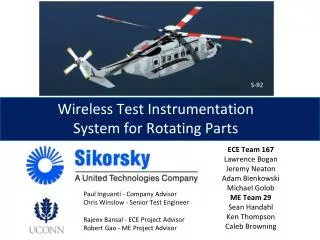
Wireless Test Instrumentation for Rotating Parts ECE 193 Advisor: Rajeev Bansal Olivia Bonner David Vold Brendon Rusch Michael Grogan ME 32 Advisor: Robert Gao Kyle Lindell Andrew Potrepka
Outline • Problem Statement • Solution • Parts Ordered • Parts To Be Ordered • Improvements To Electronics • Energy Harvesting Options • Battery Options • Future Tasks • Budget • Timeline
Problem Statement • Sikorsky has asked the team to come up with a proof of concept for a wireless sensing system. • Benefits of a Wireless System: • No long, heavy wires • No slip rings • Overall weight of system reduced • Challenges of a Wireless System: • Powering the system • Large temperature range • -65 F to 400 F
System Requirements Electronics Compartment: • Size: 1.5” diameter x 5.1” long • Temperature Range: -65ºF to 300ºF Sensor(s): • Minimum of 2 sensor types • Temperature Range: -65ºF to 400ºF Rotating Speed of Tail Rotor Shaft: • 1200 RPM
System Block Diagram Figure 1. System Block Diagram
Power Circuitry Figure 2. Power Circuitry Block Diagram
Ordered Parts • Sensor(s): • Infrared thermometer • Ambient thermometer • Accelerometer • Microphone • Microcontroller: • Arduino Nano v3.0 • Transceiver: • WiFly Module
Parts To Be Ordered • Energy Harvesting Method • Brushless Generator • Power Circuitry • Rectifier • Switching Regulator • Charging Circuit • Battery • Lithium cells (Li-Ion, Li-Poly)
Improvements to Electronics • Our Design: • Greater connectivity • Small size • Affordable • Greater available documentation • Previous Design: • Custom built, expensive to replace/modify • No documentation • Limited connectivity • Missing components
Electronics Options • New Custom Design: • Get only what we need in the size we want • Prohibitively expensive (cost > $1300) • Only can afford one • Little documentation • Off the shelf options (Arduino, Teensy): • Excellent connectivity • Available in our size • Open sourced, excellent documentation • Affordable (cost < $40)
Arduino Nano V3.0 • Small, low power evaluation board • Plenty of documented projects and code on website • Many compatible sensors/add ons for sale
Sensor/Add-on Choices • Triple axis accelerometer • Electret microphone • Ambient thermometer • Infrared thermometer • Low-power wifi module
Energy Harvesting Options • Thermoelectric • Insufficient power from available temperature gradient • Piezoelectric • Too large • Insufficient power • Needs vibrations within a narrow range of frequencies • Magnetic • Sufficient power • Requires low KV motor, gearing, or a step-up regulator • Necessitates use of gravitational torque
Battery Options • NiCd and NiMH • Quick and simple charging • Durable • Poor energy density • 1.2V per cell • Smaller temperature range • Memory (NiCd only) • Lithium cells (Li-Ion, Li-Poly) • High energy density • 3.7V per cell • Various shapes available (Li-Poly) • Wider temperature range • More complex charging • Less durable
Battery Charging Circuit Options Create our own: • Uses transistor, variable regulator, 2 capacitors, potentiometer, 1 Ohm/1 Watt resistor, 3 normal resistors
Battery Charging Circuit Options Using Power Management IC Chips: • Chip Features: • Charger Plus Pack Protection in One IC • Low Operating Current (550nA) • Near Zero Current (<0.1nA) Low Battery Disconnect Function to Protect Batteries • from Over-Discharge • Pin Selectable Float Voltage Options: 4.0V, 4.1V, 4.2V • Ultralow Power Pulsed NTC Float Conditioning for Li-Ion/Polymer Protection • Suitable for Intermittent, Continuous and Very Low Power Charging Sources • High Battery Status Output
Battery Charging Circuit Options Using Power Management IC Chips: • Chip Features: combines high-accuracy current and voltage regulation,battery conditioning, temperature monitoring, charge termination, charge-status indication, and AutoComp charge-rate compensation in a single 8-pin IC.
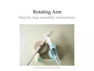
Test Rig: Potential Modifications • Different circuit – different layout inside capsule • Mount the rig to change pitch angle • Second set of wired sensors for data comparison
Tasks for Next 45 Days • Assemble and test Arduino Nano with sensors • Assemble and test Wi-Fi module • Order: motors, batteries, charging circuit equipment • Make modifications to test rig as necessary
Budget Purchase Breakdown • Budget: $2,000 • Spent to Date: $159 • Additional Estimated Costs: $350 • Estimated Surplus: $1,491
Student Assessment • Presentation Style • Readability of Material • Team results and deliverables are clear? Grade A, B, or C with clicker