Download
1 / 77
790 likes | 1.05k Views
Chapter 3 Digital Transmission Fundamentals. 3.1 Digital Representation of Information 3.2 Why Digital Communications? 3.3 Digital Representation of Analog Signals 3.4 Characterization of Communication Channels 3.5 Fundamental Limits in Digital Transmission 3.6 Line Coding

E N D
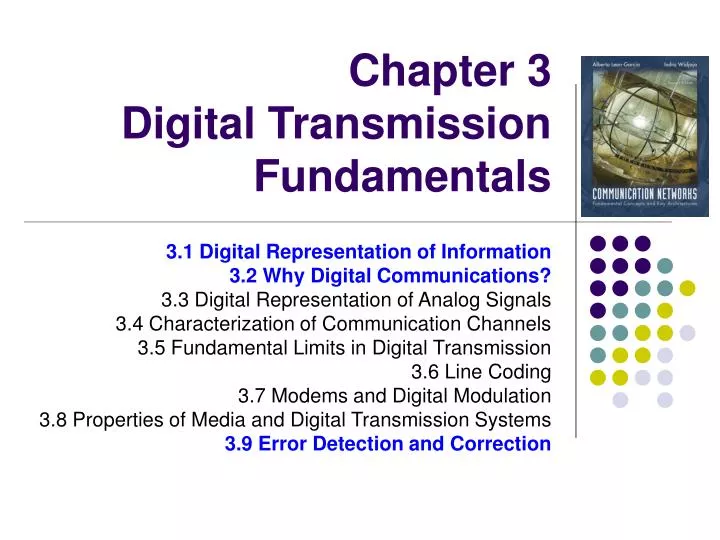
Chapter 3 Digital Transmission Fundamentals 3.1 Digital Representation of Information 3.2 Why Digital Communications? 3.3 Digital Representation of Analog Signals 3.4 Characterization of Communication Channels 3.5 Fundamental Limits in Digital Transmission 3.6 Line Coding 3.7 Modems and Digital Modulation 3.8 Properties of Media and Digital Transmission Systems 3.9 Error Detection and Correction
Digital Networks • Digital transmission enables networks to support many services E-mail TV Telephone
Questions of Interest • How long will it take to transmit a message? • How many bits are in the message (text, image)? • How fast does the network/system transfer information? • Can a network/system handle a voice (video) call? • How many bits/second does voice/video require? At what quality? • How long will it take to transmit a message without errors? • How are errors introduced? • How are errors detected and corrected? • What transmission speed is possible over radio, copper cables, fiber, infrared, …?
Chapter 3Digital Transmission Fundamentals 3.1 Digital Representation of Information
Bits, numbers, information • Bit: number with value 0 or 1 • n bits: digital representation for 0, 1, … , 2n • Byte or Octet, n = 8 • Computer word, n = 16, 32, or 64 • n bits allows enumeration of 2n possibilities • n-bit field in a header • n-bit representation of a voice sample • Message consisting of n bits • The number of bits required to represent a message is a measure of its information content • More bits → More content
Block Information that occurs in a single block Text message Data file JPEG image MPEG file Size = bits / block or bytes/block 1 Kbyte = 210 bytes 1 Mbyte = 220 bytes 1 Gbyte = 230 bytes Stream Information that is produced & transmitted continuously Real-time voice Streaming video Bit rate = bits / second 1 Kbps = 103 bps 1 Mbps = 106 bps 1 Gbps = 109 bps Block vs. Stream Information
Transmission Delay • L number of bits in message • R bps speed of digital transmission system • L/R time to transmit the information • d distance in meters • c speed of light (3x10⁸ m/s in vacuum) • tprop time for signal to propagate across medium What can be done to reduce the delay? • Use data compression to reduce L • Use higher-speed modem to increase R • Place server closer to reduce d Delay = tprop + L/R = d/c + L/R seconds
Compression • Information usually not represented efficiently • Data compression algorithms • Represent the information using fewer bits • Noiseless: original information recovered exactly • e.g., zip, compress, GIF, fax • Noisy: recover information approximately • JPEG • Tradeoff: # bits vs. quality • Compression Ratio #bits (original file) / #bits (compressed file)
W W W W H H H H Color Image Red component image Green component image Blue component image Color image = + + Total bits = 3 H W pixels B bits/pixel = 3HWB bits Example: 810 inch picture at 400 400 pixels per inch2 400 400 8 10 = 12.8 million pixels 8 bits/pixel/color 12.8 megapixels 3 bytes/pixel = 38.4 megabytes
Th e s p ee ch s i g n al l e v el v a r ie s w i th t i m(e) Stream Information • A real-time voice signal must be digitized & transmitted as it is produced • Analog signal level varies continuously in time
7D/2 5D/2 3D/2 D/2 -D/2 -3D/2 -5D/2 -7D/2 Digitization of Analog Signal • Sample analog signal in time and amplitude • Find closest approximation Original signal Sample value Approximation 3 bits / sample Rs = Bit rate = # bits/sample x # samples/second
Bit Rate of Digitized Signal • Bandwidth WsHertz: how fast the signal changes • Higher bandwidth → more frequent samples • Minimum sampling rate = 2 x Ws • Representation accuracy: range of approximation error • Higher accuracy → smaller spacing between approximation values → more bits per sample
Telephone voice Ws = 4 kHz → 8000 samples/sec 8 bits/sample Rs=8 x 8000 = 64 kbps Cellular phones use more powerful compression algorithms: 8-12 kbps CD Audio Ws = 22 kHz → 44000 samples/sec 16 bits/sample Rs=16 x 44000= 704 kbps per audio channel MP3 uses more powerful compression algorithms: 50 kbps per audio channel Example: Voice & Audio
30 fps Video Signal • Sequence of picture frames • Each picture digitized & compressed • Frame repetition rate • 10-30-60 frames/second depending on quality • Frame resolution • Small frames for videoconferencing • Standard frames for conventional broadcast TV • HDTV frames Rate = M bits/pixel x (W x H) pixels/frame x Fframes/second
176 QCIF videoconferencing (144 lines and 176 pixels per line ) 144 at 30 frames/sec = 760,000 pixels/sec 720 Broadcast TV at 30 frames/sec = 10.4 x 106 pixels/sec 480 1920 HDTV at 30 frames/sec = 67 x 106 pixels/sec 1080 Video Frames
Transmission of Stream Information • Constant bit-rate • Signals such as digitized telephone voice produce a steady stream: e.g., 64 kbps • Network must support steady transfer of signal, e.g., 64 kbps circuit • Variable bit-rate • Signals such as digitized video produce a stream that varies in bit rate, e.g., according to motion and detail in a scene • Network must support variable transfer rate of signal, e.g., packet switching or rate-smoothing with constant bit-rate circuit
Stream Service Quality Issues • Network Transmission Impairments • Delay: Is information delivered in timely fashion? • Jitter: Is information delivered in sufficiently smooth fashion? • Loss: Is information delivered without loss? If loss occurs, is delivered signal quality acceptable? • Applications & application layer protocols developed to deal with these impairments
Chapter 3 Communication Networks and Services 3.2 Why Digital Communications?
Transmitter Converts information into signalsuitable for transmission Injects energy into communications medium or channel Telephone converts voice into electric current Modem converts bits into tones Receiver Receives energy from medium Converts received signal into form suitable for delivery to user Telephone converts current into voice Modem converts tones into bits Transmitter Receiver Communication channel A Transmission System
Communication Channel Pair of copper wires Coaxial cable Radio Light in optical fiber Light in air Infrared Transmitted Signal Received Signal Transmitter Receiver Communication channel Transmission Impairments Transmission Impairments • Signal attenuation • Signal distortion • Spurious noise • Interference from other signals
Transmission segment . . . Destination Repeater Source Repeater Analog Long-Distance Communications • Each repeater attempts to restore analog signal to its original form • Restoration is imperfect • Distortion is not completely eliminated • Noise & interference is only partially removed • Signal quality decreases with # of repeaters • Communications is distance-limited • Still used in analog cable TV systems • Analogy: Copy a song using a cassette recorder
Analog transmission: all details must be reproduced accurately Sent Analog vs. Digital Transmission Distortion Attenuation Received Digital transmission: only discrete levels need to be reproduced Received Sent Distortion Attenuation Simple Receiver: Was original pulse positive or negative?
Transmission segment . . . Destination Regenerator Source Regenerator Digital Long-Distance Communications • Regenerator recovers original data sequence and retransmits on next segment • Can design it so error probability is very small • Then each regeneration is like the first time! • Analogy: copy an MP3 file • Communications is possible over very long distances • Digital systems vs. analog systems • Less power, longer distances, lower system cost • Monitoring, multiplexing, coding, encryption, protocols…
1 0 1 1 0 1 +A T 0 2T 4T 5T 6T 3T -A Digital Binary Signal Bit rate = 1 bit / T seconds For a given communications medium: • How do we increase transmission speed? • How do we achieve reliable communications? • Are there limits to speed and reliability?
Objective: Maximize pulse rate through a channel, that is, make T as small as possible Pulse Transmission Rate Channel t T t • If input is a narrow pulse, then typical output is a spread-out pulse with ringing • Question: How frequently can these pulses be transmitted without interfering with each other? • Answer: 2 x Wc pulses/second where Wc is the bandwidth of the channel
A(f) 1 f 0 Wc Bandwidth of a Channel • If input is sinusoid of frequency f, then • output is a sinusoid of same frequency f • Output is attenuated by an amount A(f) that depends on f • A(f)≈1, then input signal passes readily • A(f)≈0, then input signal is blocked • Bandwidth Wc is the range of frequencies passed by channel X(t) = a cos(2pft) Y(t) = A(f) a cos(2pft) Channel Ideal low-pass channel
Multilevel Pulse Transmission • Assume channel of bandwidth Wc, and transmit 2 Wc pulses/sec (without interference) • If pulses amplitudes are either -A or +A, then each pulse conveys 1 bit, so Bit Rate = 1 bit/pulse x 2Wc pulses/sec = 2Wc bps • If amplitudes are from {-A, -A/3, +A/3, +A}, then bit rate is 2 x 2Wc bps • By going to M = 2m amplitude levels, we achieve Bit Rate = m bits/pulse x 2Wc pulses/sec = 2mWc bps In the absence of noise, the bit rate can be increased without limit by increasing m
Noise & Reliable Communications • All physical systems have noise • Electrons always vibrate at non-zero temperature • Motion of electrons induces noise • Presence of noise limits accuracy of measurement of received signal amplitude • Errors occur if signal separation is comparable to noise level • Bit Error Rate (BER) increases with decreasing signal-to-noise ratio • Noise places a limit on how many amplitude levels can be used in pulse transmission
Signal + noise Signal Noise High SNR t t t Noise Signal + noise Signal Low SNR t t t Signal-to-Noise Ratio No errors error Average signal power SNR = Average noise power SNR (dB) = 10 log10 SNR
Shannon Channel Capacity C = Wc log2 (1 + SNR) bps • Arbitrarily reliable communications is possible if the transmission rate R < C. • If R > C, then arbitrarily reliable communications is not possible. • “Arbitrarily reliable” means the BER can be made arbitrarily small through sufficiently complex coding. • C can be used as a measure of how close a system design is to the best achievable performance. • Bandwidth Wc & SNR determine C
Example • Find the Shannon channel capacity for a telephone channel with Wc = 3400 Hz and SNR = 10000 C = 3400 log2 (1 + 10000) = 3400 log10 (10001)/log102 = 45200 bps Note that SNR = 10000 corresponds to SNR (dB) = 10 log10(10001) = 40 dB
Chapter 3Digital Transmission Fundamentals 3.9 Error Detection and Correction
Error Control • Digital transmission systems introduce errors • Applications require certain reliability level • Data applications require error-free transfer • Voice & video applications tolerate some errors • Error control used when transmission system does not meet application requirement • Error control ensures a data stream is transmitted to a certain level of accuracy despite errors • Two basic approaches: • Error detection & retransmission (ARQ) • Forward error correction (FEC)
All inputs to channel satisfy pattern or condition Channel output Deliver user information or set error alarm Pattern checking User information Encoder Channel Key Idea • All transmitted data blocks (“codewords”) satisfy a pattern • If received block doesn’t satisfy pattern, it is in error • Redundancy: only a subset of all possible blocks can be codewords • Blindspot: when channel transforms a codeword into another codeword
Info Bits: b1, b2, b3, …, bk Check Bit: bk+1= b1+ b2+ b3+ …+ bk modulo 2 Codeword: (b1, b2, b3, …, bk,, bk+!) Single Parity Check • Append an overall parity check to k information bits • All codewords have even # of 1s • Receiver checks to see if # of 1s is even • All error patterns that change an odd # of bits are detectable • All even-numbered patterns are undetectable • Parity bit used in ASCII code
Example of Single Parity Code • Information (7 bits): (0, 1, 0, 1, 1, 0, 0) • Parity Bit: b8 = 0 + 1 +0 + 1 +1 + 0 = 1 • Codeword (8 bits): (0, 1, 0, 1, 1, 0, 0, 1) • If single error in bit 3 : (0, 1, 1, 1, 1, 0, 0, 1) • # of 1’s =5, odd • Error detected • If errors in bits 3 and 5: (0, 1, 1, 1, 0, 0, 0, 1) • # of 1’s =4, even • Error not detected
Received information bits Information bits Recalculate check bits k bits Channel Calculate check bits Received check bits Compare Sent check bits Information accepted if check bits match n – k bits Check bits & Error Detection
How good is the single parity check code? • Redundancy: Single parity check code adds 1 redundant bit per k information bits: overhead = 1/(k + 1) • Coverage: all error patterns with odd # of errors can be detected • An error pattern is a binary (k + 1)-tuple with 1s where errors occur and 0’s elsewhere • Of 2k+1 binary (k + 1)-tuples, ½ are odd, so 50% of error patterns can be detected • Is it possible to detect more errors if we add more check bits? • Yes, with the right codes
P[10000000] = p(1 – p)7 = (1 – p)8 and P[11000000] = p2(1 – p)6 = (1 – p)8 p 2 1 – p p 1 – p What if bit errors are random? • Many transmission channels introduce bit errors at random, independently of each other, and with probability p • Some error patterns are more probable than others: • In any worthwhile channel p < 0.5, and so (p/(1 – p) < 1 • It follows that patterns with 1 error are more likely than patterns with 2 errors and so forth • What is the probability that an undetectable error pattern occurs?
P[undetectable error] = (10-3)2 (1 – 10-3)30 + (10-3)4 (1 – 10-3)28 ≈ 496 (10-6) + 35960 (10-12) ≈ 4.96 (10-4) P[error detection failure] = P[undetectable error pattern] = P[error patterns with even number of 1s] = p2(1 – p)n-2 + p4(1 – p)n-4 + … 32 2 32 4 n 2 n 4 Single parity check code with random bit errors • Undetectable error pattern if even # of bit errors: • Example: Evaluate above for n = 32, p = 10-3 • For this example, roughly 1 in 2000 error patterns is undetectable
Many channels have preference for error patterns that have fewer # of errors These error patterns map transmitted codeword to nearby n-tuple If codewords close to each other then detection failures will occur Good codes should maximize separation between codewords o o o o x x x o x o x o x x o o o o o o x x o o o o x x x o o o o o o x x o What is a good code? Poor distance properties x = codewords o = noncodewords Good distance properties
1 0 0 1 0 0 0 1 0 0 0 1 1 0 0 1 0 0 1 1 0 1 1 0 1 0 0 1 11 Last column consists of check bits for each row Bottom row consists of check bit for each column Two-Dimensional Parity Check • More parity bits to improve coverage • Arrange information as columns • Add single parity bit to each column • Add a final “parity” column • Used in early error control systems
1 0 0 1 0 0 0 0 0 0 0 1 1 0 0 1 0 0 1 0 0 1 1 0 1 0 0 1 1 1 1 0 0 1 0 0 0 0 0 0 0 1 1 0 0 1 0 0 1 1 0 1 1 0 1 0 0 1 1 1 Two errors One error 1 0 0 1 0 0 0 0 0 1 0 1 1 0 0 1 0 0 1 0 0 0 1 0 1 0 0 1 1 1 1 0 0 1 0 0 0 0 0 1 0 1 1 0 0 1 0 0 1 0 0 1 1 0 1 0 0 1 1 1 Three errors Four errors (undetectable) Arrows indicate failed check bits Error-detecting capability 1, 2, or 3 errors can always be detected; Not all patterns >4 errors can be detected
Other Error Detection Codes • Many applications require very low error rate • Need codes that detect the vast majority of errors • Single parity check codes do not detect enough errors • Two-dimensional codes require too many check bits • The following error detecting codes used in practice: • Internet Check Sums • CRC Polynomial Codes
Internet Checksum • Several Internet protocols (e.g., IP, TCP, UDP) use check bits to detect errors in the IP header (or in the header and data for TCP/UDP) • A checksum is calculated for header contents and included in a special field. • Checksum recalculated at every router, so algorithm selected for ease of implementation in software • Let header consist of L, 16-bit words, b0, b1, b2, ..., bL-1 • The algorithm appends a 16-bit checksum bL
Checksum Calculation The checksum bL is calculated as follows: • Treating each 16-bit word as an integer, find x = b0 + b1 + b2+ ...+ bL-1 modulo 216-1 • The checksum is then given by: bL = - x modulo 216-1 Thus, the headers must satisfy the following pattern: 0 = b0 + b1 + b2+ ...+ bL-1 + bL modulo 216-1 • The checksum calculation is carried out in software using one’s complement arithmetic