Download
1 / 10
100 likes | 202 Views
Modeling Analysis of Carbon Fiber Velvet Tested in RHEPP Ion Beam Facility. A. R. Raffray, J. Pulsifer, M. S. Tillack, X. Wang University of California, San Diego With input from T. Knowles (ESLI) and T. Renk (SNL) HAPL Review GA, San Diego April 4-5, 2002.

E N D
Modeling Analysis of Carbon Fiber Velvet Tested in RHEPP Ion Beam Facility A. R. Raffray, J. Pulsifer, M. S. Tillack, X. Wang University of California, San Diego With input from T. Knowles (ESLI) and T. Renk (SNL) HAPL Review GA, San Diego April 4-5, 2002 A. R. Raffray, et al., Modeling Analysis of Carbon Fiber Velvet Tested in RHEPP Ion Beam Facility
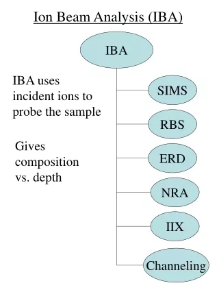
Energy Deposition as a Function of Penetration Depth in Carbon Flat Wall Under RHEPP Ion Spectra • Ion Beam data obtained from T. Renk in terms of time, voltage and current density for each ion - 5.11x10⁴ J/m2 - Energy Split: - 16% H+ - 26% C++ - 57% C+ • Energy deposition computed as a function of penetration depth for given ion spectra based on SRIM stopping power data A. R. Raffray, et al., Modeling Analysis of Carbon Fiber Velvet Tested in RHEPP Ion Beam Facility
How Does the RHEPP Energy Deposition Compares with the 154 MJ DD Target Spectra Case for R=6.5 m? • Energy Deposition fromRHEPP dominated by C ions • Energy deposition from DD target spectra dominated by deuterium and tritium ions • C and H ions have different penetration depths and energy deposition profiles • RHEPP reproduces the debris ion energy deposition level and penetration depth within a factor of 2 A. R. Raffray, et al., Modeling Analysis of Carbon Fiber Velvet Tested in RHEPP Ion Beam Facility
Volumetric Heat Generation as a Function of Space and Time in Carbon Flat Wall Under RHEPP Ion Spectra A. R. Raffray, et al., Modeling Analysis of Carbon Fiber Velvet Tested in RHEPP Ion Beam Facility
Temperature History for Carbon Flat Wall Under RHEPP Ion Spectra • Updated sublimation model for C from Philipps’ recommendation • IFE reactor-like CFC thermal conductivity as a f(T) (~235 W/m-K for T >1800 °C) - Max. Temp. 4370°C - Corresponding sublimated thickness calculated as ~ 0.032 mm per shot for 5.1x10⁴ J/m2) • Measurement from T. Renk on POCO Graphite ~20 mm after 75 shots, ~0.27 mm per shot for 5.5x10⁴ J/m2 • Not clear what grade of POCO graphite was used but k would be much lower A. R. Raffray, et al., Modeling Analysis of Carbon Fiber Velvet Tested in RHEPP Ion Beam Facility
Maximum C Temperature and Sublimation Loss per Shot as a Function of Energy Density and kcarbon for Same RHEPP Ion Energy Level • Sublimation model from Philipps’ data derived for T<4000K • As expected, thermal conductivity plays a key role and it is possible to sublimate ~1 mm per shot at energy density of 4 x10⁴ J/m2 if k < 100 W/m-K • POCO graphite seems to have low k and would be a poor material to validate CFC grade armor • It is very important to conduct experiments on well characterized material and with good diagnostics (surface T and mass loss) A. R. Raffray, et al., Modeling Analysis of Carbon Fiber Velvet Tested in RHEPP Ion Beam Facility
Carbon Fiber: Geometry Model • ESLI fiber characteristics • Fiber length 2500mm • Fiber diameter 6.5mm • Fiber k ~100-200 W/m-K • 1.5% fiber volume fraction • 98.5% void fraction • Fiber separation, y 47mm • yeff 215mm A. R. Raffray, et al., Modeling Analysis of Carbon Fiber Velvet Tested in RHEPP Ion Beam Facility
Carbon Fiber: Energy Deposition Model • Penetration depth set as a function of location in fiber based on angle of incidence and including shadowing effect from upstream fibers • Energy deposition calculated as a function of penetration depth and including angle effect which effectively increase the area seeing the ion flux A. R. Raffray, et al., Modeling Analysis of Carbon Fiber Velvet Tested in RHEPP Ion Beam Facility
Results for Carbon Fiber Under RHEPP Ion Spectrum AngleMax. Temp.(°C) Avg. Fract. Subl. Loss Left Right Fiber Tip Overall. 0° 4390 4390 1* 0.015 5.2° 4092 4352 0.43 0.0065 10° 4170 4292 0.31 0.0046 20° 4213 4041 0.15 0.0023 * Fractional sublimation loss of 1 is equivalent to ~0.032mm per shot • Sublimation loss for fiber based on temperature distribution at tip • Major difference with flat plate is very low density of fiber (0.015) • In agreement with post-experimental examination of fiber showing no visible ablation or loss of material Temperature Contour at Time Corresponding to Tmax for 10° Case A. R. Raffray, et al., Modeling Analysis of Carbon Fiber Velvet Tested in RHEPP Ion Beam Facility
Concluding Remarks from Fiber Analysis • Difficult to model flat POCO graphite case in the absence of fully characterized property data and temperature surface temperature measurement - Need to use actual material or material closely-ressembling (in properties) reactor grade armor - Need to fully characterized material properties - Need to conduct experiments with adequate diagnostics • Based on the fiber model (and consistent with experimental observation), much less material is ablated from the fiber - Incidence angle effect on local sublimation - More importantly, fiber density effect on total sublimation A. R. Raffray, et al., Modeling Analysis of Carbon Fiber Velvet Tested in RHEPP Ion Beam Facility