Download

1 / 33
520 likes | 744 Views
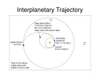
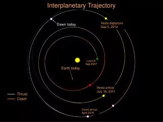
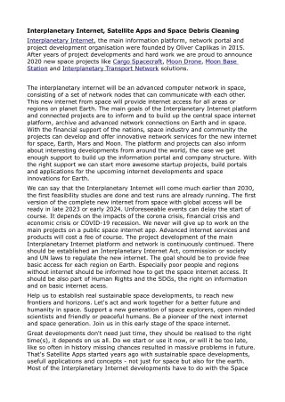
Interplanetary Trajectories. Solar System. (As of 24 Jan 1991). Interplanetary Transfer. Extension of Hohmann transfer. Once a spacecraft crosses a boundary into interplanetary space, however, Earth’s gravitational pull becomes less significant and the Sun’s pull becomes the dominant force.

E N D
Interplanetary Transfer Extension of Hohmann transfer. Once a spacecraft crosses a boundary into interplanetary space, however, Earth’s gravitational pull becomes less significant and the Sun’s pull becomes the dominant force. Therefore, because the Sun is central to interplanetary transfer, we must develop a heliocentric coordinate system.
Origin – Center of the Sun Fundamental plane – Ecliptic plane Principal direction – Vernal Equinox direction Heliocentric-ecliptic Coordinate System
Interplanetary Transfer problem N-body problem (Earth, Sun, Target planet and the spacecraft) and their gravitational effects. (How to Solve?) Gravitational forces acting on an interplanetary spacecraft
Patched-conic Approximation Divide and conquer approach for Interplanetary transfer. Breaking the interplanetary trajectory into three separate regions and considers only the gravitational attraction on the spacecraft from one body in each region.
Patched-conic Approximation Bodies moving under the influence of gravity – one of the four conic sections. Thus, the individual pieces of the spacecraft’s trajectory are conic sections. By solving one two-body problem at a time, we “patch” one conic trajectory onto another, arriving at what’s called the patched-conic approximation. Three parts of interplanetary mission by patched-conic approximation: (1) Departure phase, (2) Cruise phase, and (3) Arrival phase
Sphere of Influence (SOI) A planet’s SOI is the volume of space within which the planet’s gravitational force dominates.
Patched-conic Approximation Figure. A patched conic orbit
Interplanetary Transfer – A Simplified Example Let us consider a transfer from an orbit around an inner planet to the orbit around an outer planet. For example, to calculate the Dv required to launch a spacecraft from an orbit around the Earth (let us take LEO of 300 km altitude) to an orbit around the Mars. Assumption(s) – The orbits of Earth (planet 1) and Mars (planet 2) around the Sun are circular and coplanar.
Departure from Earth Here = The velocity of the space probe relative to the sun at the time of escaping earth. And that velocity is the velocity of the space probe on the transfer ellipse at the departure point D (perihelion in the heliocentric orbit). = the circular orbital speed of the planet 1 (here, the Earth) relative to the sun. Here | | always > | |.
Departure from Earth By subtracting the known value of ‘velocity of the planet relative to the sun’ from ‘velocity of the space probe relative to the sun’, we obtain the hyperbolic excess speed on the earth escape hyperbola. The hyperbolic excess speed can be found by calculating the required Dv at D.
Departure from Earth 2.946 km/s--- Is it the launch speed of the space probe at the orbit around the Earth?
Departure from Earth NO! --- It is the velocity of the space probe after escape from Earth. This speed is called excess speed (not the escape speed). Therefore, we have to find out what could be the velocity of the space probe relative to earth at the time of launch, , in order to achieve the excess speed of 2.946 km/s at the point of exiting the earth’s sphere of influence.
Departure from Earth Conservation of specific energy to calculate the launch speed, required to achieve excess speed of 2.946 km/s.
Departure from Earth Therefore, at this point, the Dv applied by the thrusters would be 11.3 – 7.726 = 3.574 km/s.
Departure from Earth After Earth’s SOI: Thus after applying the velocity change of 3.574 km/s to the original circular velocity of 7.726 km/s, the spacecraft (or space probe) is travelling with velocity 2.946 km/s relative to earth, or velocity of 32.73 km/s relative to the Sun.
Arrival at Mars Here = The velocity of the space probe relative to the sun at the time of approaching mars (ie.) velocity of the space probe on the transfer ellipse at the arrival point A (aphelion in the heliocentric orbit). = the circular orbital speed of the planet 2 (here, the Mars) relative to the sun. Here | | > | |
Arrival at Mars Therefore, the required Dv at A could be Plugging all the values in the above equation, 2.650 km/s.
Arrival at Mars Now the space probe is approaching Mars on a hyperbolic traj. from an infinite distance with velocity of 2.650 km/srelative to Mars.
Arrival at Mars Now, we have to find out what could be the velocity of the space probe relative to Mars at the time of reaching the orbit around the Mars ( ).
Arrival at Mars Therefore, at this point, the Dv applied by the thrusters to slow down to orbit around Mars would be km/s.
Gravity Assist Maneuver One problem with interplanetary travel is that it takes so long time. The alternative to spending long periods in heliocentric transfer orbits to reach other planets is to increase speed. Speed can be increased by expending more fuel, but it can also be increased by use of planetary gravity assist maneuver. Gravity assist maneuver – Also known as planetary flyby trajectory, slingshot maneuver, swingby trajectory.
Gravity Assist Maneuver Useful in interplanetary missions to obtain a velocity change without expending propellant. This free velocity change (not totally free) is provided by the gravitational field of the flyby planet and can be used to lower the Dv cost of a mission. This technique uses a planet’s gravitational field and orbital velocity to “sling shot” a spacecraft. Thus the spacecraft’s velocity (both magnitude and direction) changes with respect to the Sun – Thus the spacecraft’s trajectory also bend.
How does Gravity Assist work? Spacecraft passing Spacecraft passing behind a planet in front of a planet
Gravity Assist Maneuver Orbit pumping (velocity) and Orbit cranking (direction).
Gravity Assist Maneuver Slingshot referenced to the planet Mars
Gravity Assist Maneuver Slingshot referenced to the Sun
Real time Gravity-Assist Maneuvers 1. Galileo to Jupiter, NASA (1989–1995) – VEEGA
Real time Gravity-Assist Maneuvers 2. Cassini to Saturn, NASA/ESA (1997–2004)
Reference(s) Charles D. Brown, Elements of Spacecraft Design, AIAA Publications, 2002. Howard D. Curtis, Orbital Mechanics for Engineering Students, Elsevier Publications, 2005. http://web.mit.edu/12.000/www/finalpresentation/traj/hohman.html http://www.faa.gov/other_visit/aviation_industry/designees_delegations/designee_types/ame/media/Section%20III.4.1.6%20Interplanetary%20Travel.pdf http://www.philsrockets.org.uk/interplanetary.pdf “Interplanetary Flight Using the Planetary Gravity Assist Maneuver”, A Project Report by Douglas J Hopper (Available online:http://www.dept.aoe.vt.edu/~cdhall/courses/mech533/Reports92b.pdf)