Download
1 / 27
300 likes | 494 Views
Electronic Troubleshooting. Chapter 6 Power Amplifiers. Power Amplifiers. Characteristics When an amplifier deliverers more than a few milliwatts Often drives low impedance loads such as speakers Power Amps Topics Covered Complementary Symmetry Output Stage Reducing Crossover Distortion

E N D
Electronic Troubleshooting Chapter 6 Power Amplifiers
Power Amplifiers • Characteristics • When an amplifier deliverers more than a few milliwatts • Often drives low impedance loads such as speakers • Power Amps Topics Covered • Complementary Symmetry Output Stage • Reducing Crossover Distortion • Adding a Driver to the Complementary Symmetry Stage • Quasicomlementary Amps • Transformer-coupled Push-pull Circuit • High Power MOSFET Amps
Complementary Symmetry Output Stage • Characteristics • Built with a matched pair of NPN and PNP transistors • Circuit Overview • Simlified version • R1-R2 voltage divider holds both base leads at ½ Vcc • Output stabilized at the same voltage as the common base voltage
Complementary Symmetry Output Stage • Operation • Turn-on Sequence • Before the coupling Cap charges to 10V, the 10V on the base of Q1 turns it on hard • Path to ground for the emitter current is through load resistor (8Ω) • Significant current - only limited by the load resistor • As the Cap charges the Output voltage rises towards ½ Vcc • If the output goes above 10V Q1 turns off • Q2 turns on and provides a discharge path for the Cap • Once the Cap is charged to ½ Vcc both transistors are off • AC input signal applied to the common base pins through a input coupling Cap • Positive going transition • Q1 conducts
Complementary Symmetry Output Stage • Operation • AC input - continued • Positive going transition • Q1 acts like a emitter follower • Negative going transition • Q1 turns off • Q2 turns on • Notice the current flow directions • Output voltage • Peak value at a theoretical value of ½ Vcc • Theoretical Peak-Peak range • Vcc
Complementary Symmetry Output Stage • Operation • Output current • Peak value at a theoretical value of Vcc/2RL • Theoretical Peak-Peak range = Vcc/RL • Power • Needs RMS value of the AC voltages • Each transistor is on ½ of the circuit operation thus only supplies ½ of the power supplied to the load
Complementary Symmetry Output Stage • Operation • Output current • Peak value at a theoretical value of Vcc/2RL • Theoretical Peak-Peak range = Vcc/RL • Power • Needs RMS value of the AC voltages
Complementary Symmetry Output Stage • Operation • Power • Each transistor is on ½ of the circuit operation thus only supplies ½ of the power supplied to the load • The average power supplied would be equal to the power supplied during a ½ cycle spread over the full cycle (or second) – THUS ¼ of the RMS power • Sample Problem 6-1 on page 137 • In Class: 6-5, 6-6, 6-7, 6-8
Reducing Crossover Distortion • Characteristics • Neither transistor is conducting for a period of time • When vin is between +0.7 and -0.7V • The Amp off time causes a deformed output wave • Call Crossover distortion • Also generates odd harmonics
Reducing Crossover Distortion • Cure to reduce distortion • Insert a diode between the base ins of Q1 and Q2 • Operation • Both transistors are forward biased to about 0.35 V • Will reduce crossover distortion • Some distortion will remain • D1 doesn’t rectify the input • Acts like a 0.7V battery in the circuit
Adding a Driver to the Complementary Symmetry Stage (CSS) • Key Aspects • If the input signal to the CSS is too small • Add an amplifier – aka Driver to the input stage • Q3 replaces R2 in the previous drawing • Q3 acts as a directly coupled amplifier tied to the CSS • However it has a non-apparent feedback circuit • It’s voltage source is the output of the CSS
Adding a Driver • Key Aspects • Q3 acts as ~~ continued • RA and RB provide VB • Operation • Start-up • Q3 is off the moment power is applied • R1 pulls the base of Q1 towards Vcc. The emitter of Q1 (point X) follows • As point X goes positive RA pulls the base of Q3 positive and starts to turn Q3 on • When point X reaches ½ Vcc VB of Q3 should be 0.7V • If X goes to high Q3 turns on harder; then bases of Q1 & Q2 will go lower; then point X goes back to ½ Vcc
Adding a Driver • Operation • Temperature Stability • Example: If Q3 heats up and IC3 increases • Bases of Q1 and Q2 go lower • Q1 conducts less, Q2 conducts more • Voltage at point X goes lower • VB3 goes lower and IC3 decreases • Less net change due to the feedback • Real Example • Fig 6-6 on page 140 • Highlighted section • Has a circuit similar too the previous one (also on page 139) • Drawn differently with a few changes
Adding a Driver • Real Example • Highlighted section • Notice the added 1Ω emitter resisters on Q4 and Q5 • Limit current during thermal run-a-way • Help equalize the peak currents of the two transistors even if their β are different • Notice the Cap (C10) from the output to R14-R15 • It is a large cap for the AC signals that are amplified • It and the equivalent resistance have an RC time constant much larger than the period of the signal • It doesn't discharge under normal operation • C10 acts as a small battery and maintains the voltage drop across R15 constant • Thus no AC current flows through it and it appears as an open to the AC signal
Adding a Driver • Real Example • Highlighted section • Notice the Cap (C10) from the output to R14-R15 • Since R15 appears as an open the AC load seen by the driver (Q3) isn’t increased by the low resistance values of R15 & R14 • Thus the gain for Q3 is greater, AV3 = rL3/re3
Quasicomlementary Amps • Characteristics • Similar to Complementary • Used for high fidelity, high power amplifier • Analysis • Without Q4 and Q5 it is very similar to the previous circuit on page 139 • Two diodes used to further reduce crossover distortion • Q2 & Q3 biased near cutoff • Not enough current in R6 or R7 to turn either Q4 or Q5 on • Q4 and Q5 are both NPN transistors
Quasicomlementary Amps • Characteristics • Operation • Without a signal Q2 & Q3 are barely on • Minimal current in R6 & R7 • Not enough to turn Q4 or Q5 on • With signal • On positive half cycle Q2 and Q4 drive the output • With Q2 on – the voltage on R6 turns Q4 on – thus raising the output voltage • On negative half cycle Q3 and Q5 drive the output • Q3 turns on and the base of Q5 goes positive and it turns on – output goes neg
Quasicomlementary Amps • Characteristics • Actual circuit • See page 144 • Power Amplifier circuit is shown in the shaded area
Transformer-coupled Push-pull Circuit • Characteristics • Input to the power transistors is through a transformer • Center tapped • Bases of Q2 & Q3 on opposite sides of the secondary • Q2 conducts on positive transition • Q3 conducts on negative transition • Transformers selected for impedance matching • T2 – 8Ω speaker and a 10:1 turn ratio Q2 & Q3 see a 800 Ω load
Transformer-coupled Push-pull Circuit • Characteristics • Transformers • Usually have a heavier metal cores • Exact transformer replacements are critical for this type of circuit • Expensive components that are avoided in designs if Complementary Symmetry or Quasicomplementary circuits can be used for coupling • Operation • See Figure 6-12 on page 145
Transformer-coupled Push-pull Circuit • Characteristics • Real circuit • Fig 6-13 on page 146 • Uses a transformer on the input for coupling • Output stage, quasicomplementary Amp matches the load impedance • High input impedance at T1 • Less drift in output without direct coupling
High Power MOSFET Amps • Characteristics • Usually Complementary • Uses both N and P type MOSFETs • High output power over a wide frequency • i.e., 250 W, from 5 -1MHz • Usually a simpler design than comparable bipolar Amps
High Power MOSFET Amps • Characteristics • Sample circuit – Previous slide or page 147 • Only Output stage shown (missing biasing and driver circuits) • The P-type MOSFETs Q3 & Q4 have their sources tied to +75V • The N-type MOSFETs Q5 & Q6 have their sources tied to -75V • All the output transistor drains are connected to the Speaker circuit • Zener Diodes are used to prevent overdriving the output transistors with more than 8.2 V • The impedance of L1 and R7 are to balance the reactance of the load at high frequencies
High Power MOSFET Amps • Characteristics • Operation • Positive going input signal • Base of Q1 goes positive and its emitter voltage follows, but 0.7 volts lower • VGS for Q3 and Q4 goes smaller – they remain turned off • Base of Q2 goes positive, Q2conducts less, emitter goes positive • VGS for Q5 and Q6 turn on • Voltage at point X goes negative • Negative going input signal • Same type of scenario – but Point X goes positive
High Power MOSFET Amps • Troubleshooting tips • Voltage at point X should be at 0VDC w/out input • Should have 3.5 volts across both transistors • If not, probably the base biasing of either Q1 or Q2 is off • If 8.2V – check for open Q1/Q2 or biasing problem
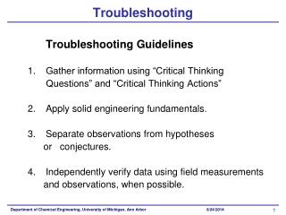
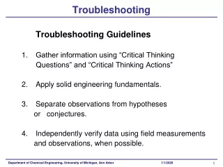
Troubleshooting • First steps – look for the obvious • Smoke • Signs of overheating • Power cord - unplugged, Fuse blown, etc • Flow Chart on page 150 • Notes on Transistor testing • Check all junction in both directions – High one way –other Low resistance • Double check all removed transistors – parallel components can cause bad in-circuit readings
Troubleshooting • Notes on replacing components • Try for exact replacements • Research any substitution parts • Shorted power transistor • Replace part and restart the system gradually using a Variable transformer as shown on page 152 • With out the full AC supply you may be able to ID a part that caused the failure of the power transistor before blowing the replacement one you installed • See test setup on page 153