Download
1 / 57
590 likes | 792 Views
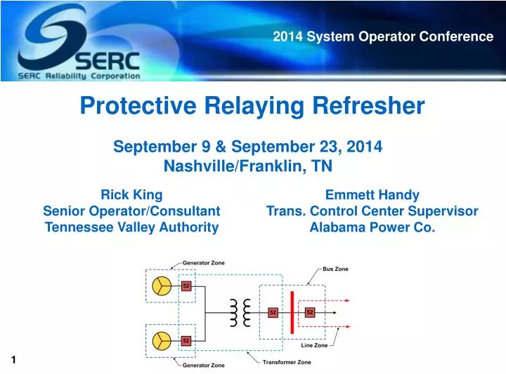
Protective Relaying Refresher. September 9 & September 23, 2014 Nashville/Franklin, TN. Rick King Senior Operator/Consultant Tennessee Valley Authority. Emmett Handy Trans . Control Center Supervisor Alabama Power Co. Terminal Objective.

E N D
Protective Relaying Refresher September 9 & September 23, 2014 Nashville/Franklin, TN Rick King Senior Operator/Consultant Tennessee Valley Authority Emmett Handy Trans. Control Center Supervisor Alabama Power Co.
Terminal Objective • At the completion of this training, participants will be familiar with the purpose and limitations of typical relay protection system schemes. • NERC Standard PRC-001-1, System Protection Coordination, Requirement 1 is the basis for this training. • Each Transmission Operator, Balancing Authority, and Generator Operator shall be familiar with the purpose and limitations of protection schemes applied in its area.
Learning Objectives At the conclusion of this training session, you should be able to: • Describe the basic types of relay protection used for power system elements, including the protection afforded. • Identify typical relay protection schemes used on typical electrical generators. • Explain the types of relay protection used on power system transmission lines. • State and discuss typical relay protection applied to power transformers. • Identify typical relay protection employed at power substations and in the switchyard.
Outline of Topics • Protective Relaying Overview • Generator Protection • Transmission Line Protection • Transformer Protection • Substation Protection • Automatic Underfrequency & Under voltage Protection • Review
Purpose of Protective Relaying Systems • Protect the bulk electric system • Remove abnormal conditions as soon as practical • Minimize the amount of customer service interrupted • Limit the damage to equipment • - NOT operate under normal conditions
ANSI/IEEE Standard Device Numbers 21 – Distance Relay: Requires a combination of high current and low voltage to operate. The various zones of the distance scheme assist with determining the location of the fault. 50 – Instantaneous Overcurrent: Operates with no time delay when current rises above a set level. 51 – Time Overcurrent: Operates on a time delay basis depending on the amount of current above a set level. 67 – Directional Overcurrent: Operates if current is above a set value and flowing in the designated direction. 79 – Reclosing Relay: Initiates an automatic closing of a circuit breaker following a trip condition. 87 – Differential Relay: Senses a difference in currents entering and leaving power system equipment.
Relay “electromagnetic or electronic device for remote or automatic control that is actuated by variation in conditions of an electric circuit, and that operates in turn other devices (as switches) in the same or different circuits”
Protective Relaying • Protective relays used by a power utility are designed to maintain system stability and minimize system disturbances by removing abnormal conditions • When a protective relay senses an abnormal condition (voltage and/or current) a command is issued to open an interrupting device • When the interrupting device opens, it removes the power source from the circuit, thereby limiting damage to system components
Function of a Protective Relay Scheme To cause the prompt removal from service of any element of a power system when: • It suffers a fault OR • It starts to operate in any abnormal manner that might cause damage or otherwise interfere with the effective operation of the rest of the system
Terminology - Faults • An event occurring on an electric system such as a short circuit, a broken wire/conductor, or an intermittent connection • Types of Faults • Phase to Ground • Phase to Phase • Three Phase • Transient
Relay Protection – Basic Types • Primary Protective Relays • Sense system parameters such as current, voltage, etc. • Initiate actions when setpoint is reached to de-energize the circuit • Backup Protective Relays • Senses same parameter as associated primary relay (Breaker Failure Relays) • Will operate & disconnect more than the faulty element to de-energize the circuit if the primary relay circuit malfunctions or the associated breaker/switch fails to operate. • Auxiliary Relays • Operates in response to primary/backup relays to assist another relay or device in performing a function
Inputs to Protective Relays (Primary) • Current Transformer – CT • Consists of many fine wires wrapped around a conductor that induces a current in the secondary directly proportional to the magnitude of amps in the primary • Resulting current flow, based on the theory of induced voltage, will be in the opposite direction to the primary current flow Output of CT can be used for Relaying or Metering
Inputs to Protective Relays (Primary) • Potential (Voltage) Transformer – PT or VT • Small transformers deriving a directly proportional ratio of the primary to the secondary voltage • Lower voltage to a more practical level to be used in metering, relaying, and synchronization on the system
Relay Protection – Basic Types Auxiliary Relay (86 - Lockout, 94 – Tripping or Trip Free) • An electrically operated relay used as a function switch to disable or enable the operations of protection and control schemes • Primary or Backup Relays actuate Auxiliary Relays • Supplement the actions of other relays • Timers • Tripping • Reclosing • Lockout relays
Generator Protection Scheme • Differential relays are used to protect generators, transformers, & buses • Operates for phase-to-phase and phase-to-ground faults Primary Fault Protection • 87 Differential • 59GN Neutral OV Primary Non-Fault Protection • 40 Loss of Field • 32 Reverse Power • 24 Volts/Hertz (59/81) Backup Protection • 21GB Gen Backup • 46 Neg. Sequence • 51 Overcurrent
Relay Protection – Differential Relays 1 Operate Coil • For external faults no current will flow through the operate coil • Given a fault anywhere between the two CTs, the conditions shown will exist • If the current flows to the fault from both directions as shown, the sum of the CT secondary currents will flow through the differential relay 1 2 2 External Fault
Generator Protection Scheme • Operates for close-in phase to ground faults • Typical generator construction has step-down transformer on wye connected ground for generator • 59GN monitors this voltage and will operate when fault current produces secondary voltage above relay setpoint • Secondary circuit normally contains resistors to limit fault current before relay operates Primary Fault Protection • 87 Differential • 59GN Neutral OV Primary Non-Fault Protection • 40 Loss of Field • 32 Reverse Power • 24 Volts/Hertz (59/81) Backup Protection • 21GB Gen Backup • 46 Neg. Sequence • 51 Overcurrent
Generator Protection Scheme • Operates when generator field current is abnormally low or has failed (loss of excitation) • On loss of field generator becomes induction vs. synchronous generator • Protects generator from high stator currents that can occur during under excited conditions • High stator currents can result in overheating & damage to stator windings & insulation Primary Fault Protection • 87 Differential • 59GN Neutral OV Primary Non-Fault Protection • 40 Loss of Field • 32 Reverse Power • 24 Volts/Hertz (59/81) Backup Protection • 21GB Gen Backup • 46 Neg. Sequence • 51 Overcurrent
Generator Protection Scheme • Uses phase to phase voltage & line current • Operates on predetermined value of power flow in a given direction (reverse power) that results from motoring of a generator upon loss of its prime mover • Typically used to protect steam driven generating units Primary Fault Protection • 87 Differential • 59GN Neutral OV Primary Non-Fault Protection • 40 Loss of Field • 32 Reverse Power • 24 Volts/Hertz (59/81) Backup Protection • 21GB Gen Backup • 46 Neg. Sequence • 51 Overcurrent
Generator Protection Scheme • Operates when ratio of volts per hertz exceeds setpoint • Protects generators & step-up transformers from damage due to excessive magnetic flux resulting from overvoltage • Excessive magnetic flux, if sustained, can cause serious overheating & may result in damage to transformer and/or generator core Primary Fault Protection • 87 Differential • 59GN Neutral OV Primary Non-Fault Protection • 40 Loss of Field • 32 Reverse Power • 24 Volts/Hertz (59/81) Backup Protection • 21GB Gen Backup • 46 Neg. Sequence • 51 Overcurrent
Generator Protection Scheme • Directional impedance type relay set to look back into generator • Can detect phase to ground & phase to phase faults in generator or associated busswork • Backs up primary fault protection relays Primary Fault Protection • 87 Differential • 59GN Neutral OV Primary Non-Fault Protection • 40 Loss of Field • 32 Reverse Power • 24 Volts/Hertz (59/81) Backup Protection • 21GB Gen Backup • 46 Neg. Sequence • 51 Overcurrent
Generator Protection Scheme • Also called Phase-Balance Current Relay • Functions when polyphase currents are unbalanced or contain negative phase sequence components • These currents in the generator stator will result in rotor overheating and will damage generator if continued operation in unbalance condition is allowed Primary Fault Protection • 87 Differential • 59GN Neutral OV Primary Non-Fault Protection • 40 Loss of Field • 32 Reverse Power • 24 Volts/Hertz (59/81) Backup Protection • 21GB Gen Backup • 46 Neg. Sequence • 51 Overcurrent
Generator Protection Scheme • Time delayed non-directional overcurrent • Protects stator windings from overheating due to overcurrent conditions • Has high current setpoint to accommodate normal load currents • Some generators use a voltage input for voltage restraint. If voltage value drops the current setpoint will also drop to a lower setting. Primary Fault Protection • 87 Differential • 59GN Neutral OV Primary Non-Fault Protection • 40 Loss of Field • 32 Reverse Power • 24 Volts/Hertz (59/81) Backup Protection • 21GB Gen Backup • 46 Neg. Sequence • 51 Overcurrent
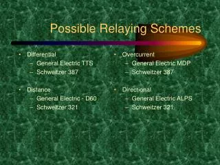
Transmission Line Protection Scheme Primary Fault Protection • 21 Directional Impedance • 67 Directional Overcurrent Backup Protection • 50BF Breaker Failure Other Relays • 79 Reclosing
Transmission Line Protection Scheme Primary Fault Protection • 21 Directional Impedance • 67 Directional Overcurrent Backup Protection • 50BF Breaker Failure Other Relays • 79 Reclosing • Used on transmission lines to measure impedance or distance to a fault & operate if the fault is within their zone of protection • Primary protection against phase to phase fault conditions • Relay divides voltage input by current input to calculate “Z” or effective impedance for line • If fault occurs outside the relays zone of protection, the impedance doesn’t change much from the perspective of relay’s location Formula relay calculates
Line Protection: Distance – Zone 1 The relays at breaker 1 are set with a Zone 1 reach of 80-85% of the protected line. Since all faults in this zone are within the protected line, no intentional time delay is introduced. Zone 1 tripping occurs instantaneously. 5 3 1 2 ZONE 1 = 85% OF PROTECTED LINE 6 Z1 4 Instantaneous
Instantaneous coverage area of both Z1 relays = the center 70% of the protected line. Line Protection: Distance – Zone 1 5 3 1 2 ZONE 1 = 85% OF PROTECTED LINE Z1 6 Z1 4 ZONE 1 = 85% OF PROTECTED LINE Instantaneous Instantaneous
Line Protection: Distance – Zone 2 The second zone reach of the relays at breaker 1 are set for a minimum of 120% of the protected line. The second zone extends beyond the end of the protected line. This is to insure that the relays will operate for all faults in the section of line between point B and breaker 2. Tripping in Zone 2 is normally delayed for about 30 cycles, but will vary depending upon the application. This time delay is for coordination purposes to give the relays on breakers 5 and 6 time to trip for a fault on their protected line. ZONE 2 = 120% OF PROTECTED LINE 5 3 Z2 B 1 2 Zone 2 Protection End of Zone 1 Protection 6 4 30 cycle delay = ½ second Delayed pickup zone for Z2 of breaker 1
30 cycle delay = ½ second Line Protection: Distance – Zone 2 Delayed pickup zone for Z2 of breaker 2 ZONE 2 = 120% OF PROTECTED LINE Z2 5 3 1 Z2 2 ZONE 2 = 120% OF PROTECTED LINE 6 4 30 cycle delay = ½ second Delayed pickup zone for Z2 of breaker 1
Line Protection: Distance – Zone 3 The primary function of the Zone 3 unit is backup protection in the event of the failure of breakers 5 or 6 or their associated relays. Zone 3 is set for 100% of the protected line plus 120% of the longest line out of the next bus. Due to line loads, length of lines, etc., it is not always possible to set the Zone 3 unit this far out. Zone 3 tripping time is set from 60 cycles and up, depending upon the application. ZONE 3 = 100% OF PROTECTED LINE PLUS 120% OF LONGEST LINE OUT OF NEXT BUS 5 3 Z3 1 2 6 4 60 cycle delay = 1 second Delayed pickup zone for Z2 of breaker 1
60 cycle delay = 1 second Line Protection: Distance – Zone 3 Delayed pickup zone for Z3 of breaker 2 ZONE 3 = 100% OF PROTECTED LINE PLUS 120% OF LONGEST LINE OUT OF NEXT BUS Z3 5 3 1 2 ZONE 3 = 100% OF PROTECTED LINE PLUS 120% OF LONGEST LINE OUT OF NEXT BUS 6 Z3 4 60 cycle delay = 1 second Delayed pickup zone for Z3 of breaker 1
Line Protection – Zone 1 Fault 60 cycle delay = 1 second 30 cycle delay = ½ second Instantaneous ZONE 3 = 100% OF PROTECTED LINE PLUS 120% OF LONGEST LINE OUT OF NEXT BUS ZONE 2 = 120% OF PROTECTED LINE Z3 ZONE 1 = 85% OF PROTECTED LINE Z2 Z1 5 3 1 2 ZONE 1 = 85% OF PROTECTED LINE ZONE 2 = 120% OF PROTECTED LINE 6 Z1 4 ZONE 3 = 100% OF PROTECTED LINE PLUS 120% OF LONGEST LINE OUT OF NEXT BUS Z2 Z3 For a fault at this location both Z1 relays at breaker 1 and breaker 2 should see the fault and operate instantaneously. Z2 and Z3 relays also see the fault, however, they are delayed in operation in order to give Z1 time to operate. Instantaneous 30 cycle delay = ½ second 60 cycle delay = 1 second
Line Protection – Zone 1 Fault 60 cycle delay = 1 second 30 cycle delay = ½ second Instantaneous ZONE 3 = 100% OF PROTECTED LINE PLUS 120% OF LONGEST LINE OUT OF NEXT BUS ZONE 2 = 120% OF PROTECTED LINE Z3 ZONE 1 = 85% OF PROTECTED LINE Z2 Z1 5 3 1 2 ZONE 1 = 85% OF PROTECTED LINE ZONE 2 = 120% OF PROTECTED LINE 6 Z1 4 ZONE 3 = 100% OF PROTECTED LINE PLUS 120% OF LONGEST LINE OUT OF NEXT BUS Z2 Z3 For a fault at this location Z1 relay at breaker 1 and Z2 relay at breaker 2 should see the fault. Z1 at breaker 1 should operate instantaneously to clear the close-in fault and Z2 at breaker 2 should operate 30 cycles later completing the isolation from the far end. Z2 and Z3 relays also see the fault, however, they are delayed in operation in order to give Z1 time to operate. Instantaneous 30 cycle delay = ½ second 60 cycle delay = 1 second
Line Protection – Zone 1 Fault 60 cycle delay = 1 second 30 cycle delay = ½ second Instantaneous ZONE 3 = 100% OF PROTECTED LINE PLUS 120% OF LONGEST LINE OUT OF NEXT BUS ZONE 2 = 120% OF PROTECTED LINE Z3 ZONE 1 = 85% OF PROTECTED LINE Z2 Z1 5 3 1 2 ZONE 1 = 85% OF PROTECTED LINE ZONE 2 = 120% OF PROTECTED LINE 6 Z1 4 ZONE 3 = 100% OF PROTECTED LINE PLUS 120% OF LONGEST LINE OUT OF NEXT BUS Z2 Z3 For a fault at this location Z2 relay at breaker 1 and Z1 relay at breaker 2 should see the fault. Z1 at breaker 2 should operate instantaneously to clear the close-in fault and Z2 at breaker 1 should operate 30 cycles later completing the isolation from the far end. Z2 and Z3 relays also see the fault, however, they are delayed in operation in order to give Z1 time to operate. Instantaneous 30 cycle delay = ½ second 60 cycle delay = 1 second
Transmission Line Protection Scheme Primary Fault Protection • 21 Directional Impedance • 67 Directional Overcurrent Backup Protection • 50BF Breaker Failure Other Relays • 79 Reclosing • Used on transmission lines primarily to detect ground faults • Operates when current exceeds a predetermined value & the fault current is in the proper direction • Directional element uses a current polarizing and/or potential polarizing input that provides directional reference • Can contain instantaneous & timed elements
Directional Overcurrent Relays • Directional Overcurrent relays have additional elements included to determine the direction of current flow through protected equipment. To accomplish directional sensing, the relay checks the relationship between input current and a “polarizing” quantity. The polarizing quantity is simply a reference from which the relay can determine power flow direction. • The polarizing quantity can be voltage or a current. • Voltage = Voltage polarizing • Current = Current polarizing M M Current inputs Current inputs Directional O.C. Directional O.C. Polarizing Input V= Voltage I = Current Polarizing Input V= Voltage I = Current
Directional Overcurrent Relays • Directional Overcurrent Relays may be used to protect transmission lines between substations, where power can flow in either direction. Directional overcurrent relays are “more sensitive” than non-directional relays. • Directional relays are used to confine relay operations to one particular line section. The relay will only trip for faults in the line it is responsible for. Fault Current Flow Extremely High Current Normal Current Flow M M Current inputs Current inputs Directional O.C. Directional O.C. Polarizing Input V= Voltage I = Current Polarizing Input V= Voltage I = Current
Line Protection: Overcurrent – Directional Due to the sensitivity of the directional elements in these relays, they can/will pick up for normal load if power flow is in the same direction for which the relay is connected to operate. Therefore, at terminals where normal load flow can keep the directional element picked up, the overcurrent unit must be set high enough to insure that they won't operate for maximum load current flow in the tripping direction. Change Tap Settings or ALT SET APPLIED to prevent “overcurrent” element from picking up and tripping when abnormal line configurations occur. Overcurrent element not picked up = current is not beyond trip set point for protected line TRIP Directional element picked up = current is flowing “into” the protected line
Transmission Line Protection Scheme • Provides system backup protection in the event of a circuit breaker failing to open on a trip signal • Accomplished by applying a trip signal from the primary relays to the breaker failure relay, if breaker still passing current after 15-17 cycle time delay then 50BF will send trip signal to other breakers on same bus and other paired breaker • Relay initiation is stopped by either absence of trip signal from primary relays or by current flow through breaker dropping below a preset level Primary Fault Protection • 21 Directional Impedance • 67 Directional Overcurrent Backup Protection • 50BF Breaker Failure Other Relays • 79 Reclosing
Relay Protection – Breaker Failure Relays X Breaker failure initiates tripping to the backup breakers within a preset time delay of 15 to 17 cycles after the original trip signal initiated
Transmission Line Protection Scheme Primary Fault Protection • 21 Directional Impedance • 67 Directional Overcurrent Backup Protection • 50BF Breaker Failure Other Relays • 79 Reclosing • Controls the automatic reclosing and locking out of an AC circuit interrupter (PCB) • Reclosing occurs after protective relay operation on a transmission line • Reclose capability controlled by Transmission Operators • Types of reclosing used: • High speed (~20 cycles) • Fast speed (~45 cycles) • Standard speed (varies based on configuration) • If reclosing is unsuccessful, reclose relay locks out breaker
Transformer Protection Scheme Primary Fault Protection • 87 Differential • 63 Sudden Pressure Backup Protection • 51N Neutral Overcurrent • 51 Phase Overcurrent
Transformer Protection Scheme Primary Fault Protection • 87 Differential • 63 Sudden Pressure Backup Protection • 51N Neutral Overcurrent • 51 Phase Overcurrent • Relay will operate for phase to phase or phase to ground fault within monitored area • Monitors for imbalance or current flow through CTs bounding monitoring area • Transformer differential relays may contain a harmonic restraint unit 2 Would the 87 relay actuate for a fault at location 1? 1 What about location 2?
Transformer Protection Scheme Primary Fault Protection • 87 Differential • 63 Sudden Pressure Backup Protection • 51N Neutral Overcurrent • 51 Phase Overcurrent • Detects internal faults for power transformers & regulators (tap changers) • Responds to a fast rise in internal pressure produced by an internal fault • Capable of detecting faults below sensitivity level of differential relays • Typically mounted on the side or top of the transformer
Transformer Protection Scheme Primary Fault Protection • 87 Differential • 63 Sudden Pressure Backup Protection • 51N Neutral Overcurrent • 51 Phase Overcurrent • Time delay overcurrent that monitors neutral of transformer winding • Can have a definite or inverse time characteristic that functions when ac input current exceeds a predetermined value • Senses ground faults on that side (typically secondary) of transformer and initiates protective action
Transformer Protection Scheme Primary Fault Protection • 87 Differential • 63 Sudden Pressure Backup Protection • 51N Neutral Overcurrent • 51 Phase Overcurrent • Non-directional, operates when current in operating element exceeds relay’s minimum trip setting • Relay must be set higher than anticipated load current, yet operate to provide adequate protection for faults • Relay can contain an instantaneous (50) and/or timed (51) element
Relay Protection – Residual Ground Relay (64) • Normal balanced load conditions, no current in the ground relay • Only when one phase becomes faulted will there be appreciable current flow in this portion of the circuit 5
Substation (Bus) Protection Scheme Primary Fault Protection • 87 Bus Differential • 87FD Feeder Differential
Bus Differential Protection Breakers may / may not be configured to trip, depending on downstream sources. BUS DIFFERENTIAL= Operates for faults detected on the bus. Separate protection is provided for the transformer bank. Protected Zone 3 Trip 1 Trip 4 Trip Output Trip Current Input Current Input Current Input Differential Relay