Download
1 / 18
190 likes | 370 Views
Tyler Martin Zebedee Smith Phillip Chukwu. Attenuation due to Connectors and Splices. Overlap of fiber cores. The fibers may be parallel, but ate not lined up vertically. Light leaks out of the core of the first fiber into the cladding of the second fiber. Diameter Overlapping.

E N D
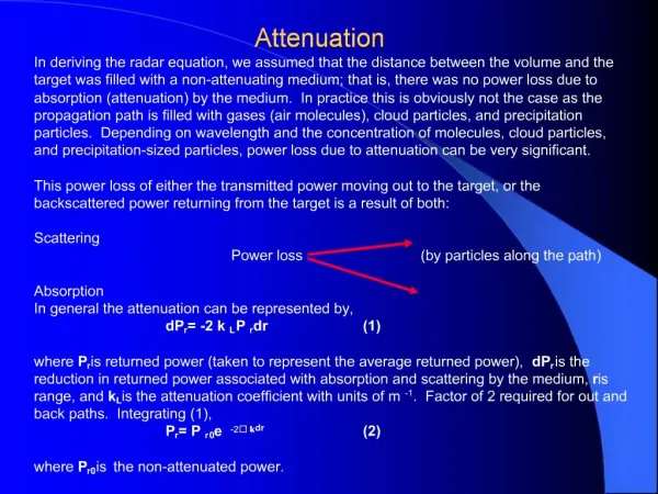
Tyler Martin Zebedee Smith Phillip Chukwu Attenuation due to Connectors and Splices
Overlap of fiber cores • The fibers may be parallel, but ate not lined up vertically. • Light leaks out of the core of the first fiber into the cladding of the second fiber.
Diameter Overlapping • Differences in the diameter of the cores will also create overlapping. • The loss due to this can be found as: Loss = (d12 – d22 / d12 • Where d1 is the diameter of the core of the sending fiber, and d2 is the diameter of the core of the receiving fiber.
Example • Example: Calculate the loss due to overlapping if the diameter of the receiving fiber core is 9µm and the diameter of the sending fiber core is 15 µm.
Others • Problems also occur from differences in fiber types, and when there are elliptical and off0centered cores.
Alignment of Fiber Axes • This simply refers to the angle of difference. • Fibers with a higher Numerical Aperture can collect light over a large range of angles.
Spacing between fibers • There are two ways that light can be lost if there is any spacing between the fibers. • There is the spreading of the light when it leaves a fiber. • There is the reflection of light passing between materials.
Spacing between fibers(END-SEPERATION LOSS) • Light leaves fibers in a cone shape • The spreading angle of the light is dependent on the numerical aperture. • The loss increases as the NA of the input fiber increases because a higher NA causes the light to spread faster. • The more the light spreads the less light the receiving fiber will collect.
Spacing between fibers(END-SEPERATION LOSS) • The equation for loss is • d is the core diameter • S is the fiber spacing • NA is the numerical aperture • n0 is the refractive index of the material between the fibers
End-reflection loss • Another way light can be lost through spacing between the fibers is through end-reflection loss. • This occurs when light passes between two materials with different refractive indexes. This process is called Fresnel Reflection.
End-reflection loss • The equation for the fraction of light reflected is • R is fraction of light reflected • nfiber is the refractive index of the fiber where light is coming from • n is the refractive index of the object where the light is heading to
End-reflection loss • The equation for loss in dB is • This gives the loss per glass-air interface.
Example • Find the End-reflection loss in dB if the fiber core is made of glass and the gap is air.