Download
1 / 21
210 likes | 349 Views
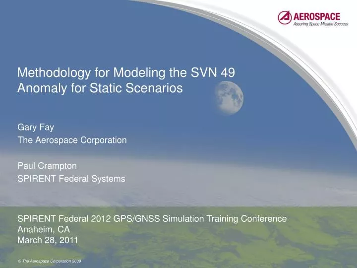
Methodology for Modeling the SVN 49 Anomaly for Static Scenarios. Gary Fay The Aerospace Corporation Paul Crampton SPIRENT Federal Systems. SPIRENT Federal 2012 GPS/GNSS Simulation Training Conference Anaheim, CA March 28, 2011. Introduction.

E N D
Methodology for Modeling the SVN 49 Anomaly for Static Scenarios Gary Fay The Aerospace Corporation Paul Crampton SPIRENT Federal Systems SPIRENT Federal 2012 GPS/GNSS Simulation Training Conference Anaheim, CA March 28, 2011
Introduction • GPS Satellite Vehicle Number (SVN) 49 is transmitting an anomalous delayed version of the L1/L2 signals • The root cause of the anomalous signal is reviewed • A method is desired for simulating the anomalous signals to determine the impact to civilian and military receivers if the satellite were to be set healthy • The pseudorange error due to the delayed signals is modeled using multipath theory • Two scenarios for simulating this model were developed • Comparison of theoretical, simulated, and live results is presented • The paper provides all technical information needed to model the SVN 49 anomaly on any simulator • Scenarios are being made publicly available by SPIRENT to model the SVN 49 anomaly on SPIRENT simulators
Background • GPS IIR-20(M), also designated SVN 49, was launched onMarch 24, 2009 • Supposed to broadcast PRN 1 code signal replacing GPS IIA-27 • Initial on-orbit diagnostic testing by 2SOPS and Aerospace revealed that the transmitted L1/L2 signals produced anomalous pseudorange measurements • SVN 49 carried a demonstration payload to broadcast the new civilian L5 frequency to meet deadlines for reserving the spectrum with the International Telecommunication Union (ITU) • The L5 demonstration payload used a spare coupling port, called J2, to transmit the L5 signal • The J2 port is normally terminated • The J2 port was previously used successfully with a different payload 3
Background • A thorough fault tree analysis was completed • The determination of the root cause is that: • The L1/L2 signals leak through the input coupler of the antenna power divider onto the J2 input line • The leaked signals reflect off the L5 bandpass filter due to an impedance mismatch • The reflected signal reenter the J2 port and are broadcast by the GPS antenna array • Turning the L5 demonstration payload off does not affect the reflection 4
GPS Satellite Antenna Array • GPS antenna array consists of an eight element outer ring and four element inner ring • The rings shape the transmission pattern for the GPS signals • The inner ring transmits a wide beam • The outer ring transmits a narrowly focused beam • A power divider splits power between inner and outer rings • Power to elements in the same ring is equal 5
GPS Satellite Antenna Patterns • Transmission patterns for the inner ring, outer ring, and combined power are plotted versus boresight angle • The GPS antenna array is designed to radiate equal power to the Earth’s surface that is visible to the satellite • More power must be transmitted to Earth’s limb due to curvature of the Earth and signal propagation losses • Requires ~3 dB increase in power at 14 degrees boresight 6
GPS Satellite Antenna Electronics • The power divider distribues energy from the signal input ports to elements in the inner and outer rings for beam shaping • The Input Coupler sends 79% of the power from the J1 port to the inner ring and 21% to the outer ring • This gives the beam pattern shown on the last slide • By contrast, 21% of the power from the J2 port is sent to the inner ring and 79% is sent to the outer ring 7
Root Cause of the SVN 49 Anomaly • L1/L2 signal energy at J1 port leaks through the Input Coupler to the J2 input line • Leaked signal reflects off the bandpass filter of the L5 demonstration payload due to an impedance mismatch • The reflected L1/L2 signals reenter the J2 port and are transmitted according to the J2 beam pattern 8
Measured Antenna Patterns for Signals Injected Into the J1 and J2 Ports • Lockheed Martin measured beam patterns in an anechoic chamber using an actual GPS satellite antenna array and electronics • The blue lines are for a signal injected into the J1 port and the red lines are for an equal power signal injected into the J2 port L2 Frequency Measurements L1 Frequency Measurements 9
Analysis of the SVN 49 Psuedorange Error Using Braasch Multipath Equations • The reflected signal from SVN 49 impacts the receiver in exactly the same way that a multipath signal does • Correlation function of combined signal is distorted due to reflection • Asymmetry of the distorted correlation function causes an Early-minus-Late Delay Lock Loop (DLL) to miscalculate the correlation peak location • The error in the estimated peak location is directly proportional to the error in estimated psuedorange • The pseudorange error is given by the Braasch multipath equation: 10
Relative Gain and Phase Between the Primary and Reflected Signals • Relative gain, G, and phase, , between the primary and reflected signal are derived from the anechoic chamber data and plotted as a function of elevation • The power ratio term is computed by interpolating for the value of G and at a given elevation 11
Theoretical Psuedorange Error for SVN 49 as a Function of Elevation • The delay of the reflected signal from SVN 49 is fixed, unlike true multipath • Measured as 38 ns • The Braasch multipath equation is perfectly valid to model the pseudorange error due to the SVN 49 anomalous signal • Theoretical psuedorange error is calculated by plugging the power ratio, , at a given elevation into the Braasch multipath equation 12
Methodology for Simulating the SVN 49 Anomaly • Depending on the capabilities of a given GPS constellation simulator, the delayed reflection transmitted from SVN 49 can be simulated as • A fixed delay multipath signal • A signal from a fictitious satellite collocated with SVN 49 • For a general approach, the GPS constellation simulator should individually modify the gain and phase patterns of the multipath signal or the second satellite signal to achieve the relative gain and phase differences plotted previously • The SimGEN program used to generate scenarios for SPIRENT simulators has a master gain and phase pattern for all satellites, but does not have the capability to define separate gain and phase patterns for individual satellites or multipath signals • A workaround was achieved by using User Command Data (.ucd) files to program gain and phase as a function of time for a given scenario 13
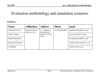
Aerospace SVN 49 Anomaly Simulation Testing Using SPIRENT Scenarios • Two L1/L2 scenarios were developed for use on Spirent simulators • Operational Scenario • Simulates a fixed position receiver directly on the ground track of SVN-49 in the North Pacific • Full constellation flown with SVN 49 set healthy • A control satellite collocated with SVN 49 can be used for pseudorange error measurements, or disabled to assess the impact on position error • Calibration Scenario • SVN 49 is collocated with a control satellite in geosynchronous orbit • SPIRENT (.ucd) files used to simulate a decrement of one degree of elevation every 30 seconds; entire calibration for SVN 49 from zentith to horizon is completed in 45 minutes • Fictitious 1000 m/s Doppler added to control satellite signal to eliminate cross-correlation interference; removed during post-processing 14
Live Results from 30-meter Dish Measured by DLR in Weilheim, Germany L2 Measured Pseudorange Error L1 Measured Pseudorange Error 15
Live Results from Cold Bay, Alaska Data vs.Simulated results from SPAWAR AGNS Simulator
Simulation Results for Pseudorange Error from the Calibration Scenario
Simulation Results for Psuedorange Error from the Operational Scenario
Conclusion • A method to successfully model the SVN 49 pseudorange error using Braasch multipath equations was described • Two SPIRENT simulator scenarios were developed to implement this model for a stationary receiver • Comparison of the simulator results to the theoretical estimate and live data show excellent agreement • A procedure to automate the creation of (.ucd) files for a generic scenario is being developed • SPIRENT simulator scenarios are being made publicly available at:www.spirentfederal.com/GPS/SVN_49/ 21