Download
1 / 19
190 likes | 192 Views
This paper discusses the phenomenon of resistance drift in phase change memory (PCM) and proposes various device, circuit, architecture, and system-level solutions to mitigate its effects. Resistance drift becomes increasingly significant as the number of levels/cells in PCM devices increases, leading to soft errors. Naïve techniques based on DRAM-like refresh are costly in terms of latency and energy. The paper explores holistic solutions to counter drift in multi-level cells (MLCs) of PCM.

E N D
Handling Resistance Drift in Phase Change Memory - Device, Circuit, Architecture, and System Solutions Manu Awasthi⁺, ManjunathShevgoor⁺, Kshitij Sudan⁺, Rajeev Balasubramonian⁺, BipinRajendran‡, VijiSrinivasan‡ ⁺University of Utah, ‡IBM Research
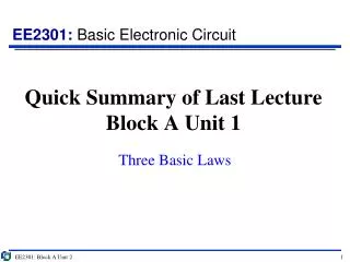
Quick Summary • Multi level cells in PCM appear imminent • A number of proposals exist to handle hard errors and lifetime issues of PCM devices • Resistance Drift is a lesser explored phenomenon • Will become increasingly significant as number of levels/cell increases – primary cause of “soft errors” • Naïve techniques based on DRAM-like refresh will be extremely costly for both latency and energy • Need to explore holistic solutions to counter drift
Phase Change Memory - MLC • Chalcogenide material can exist in crystalline or amorphous states • The material can also be programmed into intermediate states • Leads to many intermediate states, paving way for Multi Level Cells (MLCs) (01) (11) (10) (00) Crystalline Amorphous Resistance (110) (101) (100) (011) (010) (001) (111) (000)
What is Resistance Drift? Time 11 10 01 00 ERROR!! Tn B T0 A Resistance
Resistance Drift - Issues • Programmed resistance drifts according to power law equation - • R0, α usually follow a Gaussian distribution • Time to drift (error) depends on • Programmed resistance (R0), and • Drift Coefficient (α) • Is highly unpredictable!! Rdrift(t) = R0х (t)α
Resistance Drift - How it happens ERROR!! 11 10 01 00 Number of Cells R0 R0 Rt Rt • Median case cell • Typical R0 • Typical α • Worst case cell • High R0 • High α Scrub rate will be dictated by the Worst Case R0 and Worst Case α
Resistance Drift Data (11) (01) (10) (00)
Naïve Solution • Drift resets with every cell reprogram (write) • Leverage existing error correction mechanisms e.g. ECC - has its own drawbacks • A Full Refresh (read-compare-write) is extremely costly in PCM • Each PCM write takes 100 - 1000ns • Writing to a 2-bit cell may consume as much as 1.6nJ • Requires 600 refreshes in parallel Refresh should be reactionary NOT precautionary!
Architectural Solutions - LARDD • Light Array Reads for Drift Detection • Support for N Error-correcting, N+1 error detecting codes assumed • Lines are read periodically and checked for correctness • Only after the number of errors reaches a threshold, scrubbingis performed Read Line Check for Errors True Errors < N After N cycles False Scrub Line
Architectural Solutions - Headroom • Headroom-h scheme – scrub is triggered if N-h errors are detected • Decreases probabilityof errors slipping through • Increases frequency of full scrub and hence decreases life time • Presents trade-off between Hard and Soft errors Read Line Check for Errors True Errors < N-h After N cycles False Scrub Line
Solutions Summary Architectural Device • Headroom schemes • Trade off between error rates and lifetime • Precise writes • Guardbanding Circuit System • Parity based technique • Makes common case faster • Reduces overheads • Varying scrub rates • Accounts for changes in operating conditions • Temperature • Hard errors
System Level Solutions • Dynamic events can affect reliability • Temperature increases can increase α and decrease drift time • Cell lifetime/wearout is also an issue • Soft error rate depends on prevalence of drift prone states • These effects should be taken into account to dynamically adjust LARDD frequency • Start with a low LARDD rate • Double rate when errors exceed pre-set threshold • Mark line as defunct when hard errors exceed pre-set threshold
Reducing Overheads with Circuit Level Solution • Invoking ECC on every LARDD increases energy consumption • Parity – like error detection circuit is used to signal the need for a full fledged ECC error detect • Number of Drift Prone States in each line are counted when the line is written into memory • 0 is stored as a Flag for even number of Drift Prone States , 1 for odd • The Flag is computed at each LARDD • A Flag mismatch invokes a full-fledged ECC • Reduces need for ECC read-compare at every LARDD cycle (11) (01) (10) (00) 13
Device Level Solution – Precise Write Write Mean R Resistance Boundary Thresholds
Device Level Solution – Precise Write Write Mean R Resistance Boundary Thresholds Precise Writes help alleviate drift at device level but takes longer and hurts lifetime!
Device Level Solution – Non Uniform Banding Before Mean R0 11 10 01 00 After Resistance
Solutions Summary Architectural Device • Headroom schemes • Trade off between error rates and lifetime Error rates vs write energy • Precise writes • Guardbanding • Trades off between error rate write energy Error rates vs lifetime Circuit System • Parity based technique • Makes common case faster • Reduces overheads • Varying scrub rates • Accounts for changes in operating conditions • Temperature • Hard errors Accounts for varying conditions Reduces ECC overheads
Conclusions • Resistance drift will exacerbate with MLC scaling • Naïve solutions based on ECC support are costly for PCM • Increased write energy, decreased lifetimes • Holistic solutions need to be explored to counter drift at device, architectural and system levels • 39% reduction in energy, 4x less errors, 102x increase in lifetime • Work in progress!!