Download
1 / 17
170 likes | 174 Views
This lecture covers the topics of logistics, multiplexers, and demultiplexers in switching networks. The lecture materials include examples of K-map minimization, design examples, and the construction of these devices using logic gates. The lecture also discusses the concept of sharing complex logic functions through the use of multiplexers. Homework 3 is due on Friday and covers the materials up to this lecture. The lab for this week is Lab 3 and Midterm 1 is scheduled for a week from today, covering the materials up to this lecture. This is the last lecture before the midterm.

E N D
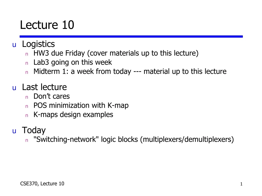
Lecture 10 • Logistics • HW3 due Friday (cover materials up to this lecture) • Lab3 going on this week • Midterm 1: a week from today --- material up to this lecture • Last lecture • Don’t cares • POS minimization with K-map • K-maps design examples • Today • "Switching-network" logic blocks (multiplexers/demultiplexers)
Switching-network logic blocks • Multiplexer (MUX) • Routes one of many inputs to a single output • Also called a selector • Demultiplexer (DEMUX) • Routes a single input to one of many outputs • Also called a decoder multiplexer demultiplexer • We construct these • devices from: • logic gates • networks of tran- • sistor switches control control
The “WHY” slide • Multiplexers/Demultiplexers • If you had the ability to select which input to operate, the same part of a circuit can be used multiple times. So if you have a lot of inputs and all of them are supposed to go through same complex logic functions, you can save a lot of space on your circuit board by using a multiplexer. • Then you will also need a demultiplexer to decode the output coming out in serial into separate output ports.
A0 A1 B0 B1 Sb MUX MUX B A Sum Ss DEMUX Z0 Z1 “WHY”: Sharing complex logic functions • Share an adder: Select inputs; route sum multiple inputs Sa single adder multiple output destinations
In1 In0 S Z0 0 0 00 0 1 00 1 0 10 1 1 01 0 0 01 0 1 11 1 0 11 1 1 1In1 In0 S Z0 0 0 00 0 1 00 1 0 10 1 1 01 0 0 01 0 1 11 1 0 11 1 1 1 S Z0 In01 In1 Multiplexers • Basic concept • 2n data inputs; n control inputs ("selects"); 1 output • Connects one of 2n inputs to the output • “Selects” decide which input connects to output • Two alternative truth-tables: Functional and Logical Functional truth table Logical truth table Example: A 2:1 Mux Z = SIn1 + S'Ino I0 Z S I1
Multiplexers (con't) • 2:1 mux: Z = S'In0 + SIn1 • 4:1 mux: Z = S0'S1'In0 + S0'S1In1 + S0S1'In2 + S0S1In3 • 8:1 mux: Z = S0'S1'S2'In0 + S0'S1S2In1 + ... I0I1 I0I1I2I3 I0I1I2I3I4I5I6I7 2:1mux Z 4:1mux Z 8:1mux Z S0 S0 S1 S0 S1 S2
I0 S I1 Logic-gate implementation of multiplexers 2:1 mux 4:1 mux I0 I1 I2 I3 Z Z Z S0 S1
Cascading multiplexers • Can form large multiplexers from smaller ones • Many implementation options 8:1 mux 8:1 mux I0I1I2I3 I0I1 2:1mux 4:1mux I2I3 2:1mux 2:1mux Z 4:1mux Z I4I5I6I7 4:1mux I4I5 2:1mux I6I7 2:1mux S0 S1 S2 S1 S2 S0
Multiplexers as general-purpose logic • A 2n:1 mux can implement any function of n variables • A lookup table • A 2n – 1:1 mux also can implement any function of n variables • Example: F(A,B,C) = m0 + m2 + m6 + m7 = A'B'C' + A'BC' + ABC' + ABC = A'B'(C') + A'B(C') + AB(0) + AB(1) A B C F0 0 0 10 0 1 00 1 0 10 1 1 01 0 0 01 0 1 01 1 0 11 1 1 1 10100011 01234567 C'C'01 C'C'01 0123 F F 8:1 MUX 4:1 MUX S1 S0 S2 S1 S0 A B A B C
Multiplexers as general-purpose logic • Implementing a 2n-1:1 mux as a function of n variables • (n-1) mux control variables S0 – Sn–1 • One data variable Sn • Four possible values for each data input: 0, 1, Sn, Sn' • Example: F(A,B,C,D) implemented using an 8:1 mux A AB 00 01 11 10 1D01D'DD'D' CD 01234567 Choose A,B,C as control variables Choose D as a data variable 1 0 1 1 1 0 0 0 1 1 0 1 0 1 1 0 00 8:1 MUX F 01 D 11 C S2 S1 S0 10 B A B C
Demultiplexers (DEMUX) • Basic concept • Single data input; n control inputs (“selects”); 2n outputs • Single input connects to one of 2n outputs • “Selects” decide which output is connected to the input • When used as a decoder, the input is called an “enable” (G) 1:2 Decoder: Out0 = G S' Out1 = G S 2:4 Decoder: Out0 = G S1' S0' Out1 = G S1' S0 Out2 = G S1 S0' Out3 = G S1 S0 3:8 Decoder: Out0 = G S2' S1' S0' Out1 = G S2' S1' S0 Out2 = G S2' S1 S0' Out3 = G S2' S1 S0 Out4 = G S2 S1' S0' Out5 = G S2 S1' S0 Out6 = G S2 S1 S0' Out7 = G S2 S1 S0
G Out0 Out1 Out2 Out3 S1 S0 Logic-gate implementation of demultiplexers 1:2 demux 2:4 demux Out0 G S Out1
Demultiplexers as general-purpose logic • A n:2n demux can implement any function of n variables • DEMUX as logic building block • Use variables as select inputs • Tie enable input to logic 1 • Sum the appropriate minterms (extra OR gate) demultiplexer “decodes” appropriate minterms from the control signals 0 A'B'C'1 A'B'C2 A'BC'3 A'BC4 AB'C'5 AB'C6 ABC'7 ABC 3:8 Demux 1 S2 S1 S0 A B C
Demultiplexers as general-purpose logic Example F1 = A'BC'D + A'B'CD + ABCD F2 = ABC'D' + ABC F3 = (A'+B'+C'+D') 0 A'B'C'D'1 A'B'C'D2 A'B'CD'3 A'B'CD4 A'BC'D'5 A'BC'D6 A'BCD'7 A'BCD8 AB'C'D'9 AB'C'D10 AB'CD'11 AB'CD12 ABC'D'13 ABC'D14 ABCD'15 ABCD F1 4:16Demux Enable = 1 F2 F3 A B C D
Cascading demultiplexers • 5:32 demux 0 A'B'C'D'E'1234567 012 A'BC'DE'34567 3:8 Demux 3:8 Demux S2 S1 S0 S2 S1 S0 0123 2:4 Demux F S1 S0 01234567 ABCDE 0 AB'C'D'E'1234567 AB'CDE A B 3:8 Demux 3:8 Demux S2 S1 S0 S2 S1 S0 C D C D E E
Programmable logic (PLAs & PALs ) • Concept: Large array of uncommitted AND/OR gates • Actually NAND/NOR gates • You program the array by making or breaking connections • Programmable block for sum-of-products logic • • • inputs ANDarray ORarray productterms outputs • • •
All two-level logic functions are available • You "program" the wire connections A 3-input, 5-term, 4-function PLA