Download
1 / 27
270 likes | 354 Views
Tonga Institute of Higher Education. IT253: Computer Organization. Lecture 9: Making a Processor: Single-Cycle Processor Design. The big picture. Where are we now in the computer picture? The datapath is the way the computer implements the instruction set (like MIPS)

E N D
Tonga Institute of Higher Education IT253: Computer Organization Lecture 9: Making a Processor: Single-Cycle Processor Design
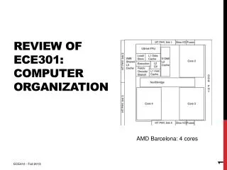
The big picture • Where are we now in the computer picture? • The datapath is the way the computer implements the instruction set (like MIPS) • It is obviously an important part of the processor. • When we understand the datapath, we will understand most of the processor
MIPS and the datapath • Remember MIPS uses instruction formatting to convert text into binary numbers. • These numbers will be what the datapath reads in and executes. • In MIPS they are 32 bits long and have different fields. • This is how we will build our processor
Building a Datapath • So what hardware pieces (gates and circuits) do we need to implement the MIPS instructions? • We will need an Adder, a MUX, and an ALU
Memory Circuits • So far all the circuits we have made will give us an output, which we can use to perform operations • We also need a way to save memory (like a register). There are a few ways that we can save a value in a circuit. • The output of these circuits that remember values is the result of the value inside. • These are called “sequential” circuits
Building a Datapath: The Clock • We will be talking about devices called clocks in this chapter. • Because computers need things to happen in a certain order, they need to be synchronized • To be synchronized, computers will use clocks which are a series of pulses that has a very accurate width and interval between pulses • The time interval between pulses is called the clock cycle time. • A 500 MHz processor has a clock cycle of 2 nanoseconds. This means every 2 nano-seconds (2 billionths of a second) the processor can execute another operation
Set-Reset Latch • One simple memory element is called the Set-Reset Latch
Tri-State Driver • A tri-state driver is a one-directional switch. • When it is enabled (E=1), output = input • When it is not enabled (E=0), the output is physically disconnected from the gate's internal circuitry. This state is normally called "floating" • The output is neither logic high or low, instead it floats and appears as a very high resistance on the circuit, in effect the Tri-state device is disconnected from the circuit. • This will allow whatever value was Q before to remain
What can we do with those? • With memory elements and the tri-state driver we can make circuits that save memory addresses and decode them. • We can also save values in registers • We can also use a tri-state driver to choose one thing from among many, like on a data bus ( a wire that connects many devices).
Building a Datapath: Memory • We need a way to store things • The storage element we will use is called a “register” • This is like the memory element we talked about in MIPS • The Set-Reset Latch. • “Register” memory uses N bits for input and output. • There must be a "Write Enable" option. • If the input to "Write enable" is: • 1 - then the register will output the numbers from Data In • 0 – then the output will not change from what it was before
Building a Datapath: Lots of Memory • We need to store 32 registers, so we create what is called a “register file” • A register file is 32 registers put together into one little box • It also has two 32 bit outputs (busA and busB) and one 32 bit input (busW) • RA selects the register that will go onto bus A • RB selects the register that will go onto bus B • RW selects the register that will be changed by the input (busW) if Write Enable = 1 Clk = Clock – the input that will run the cycle of the register file. After a clock cycle, something will have happened (either output or a write)
Datapath: Putting pieces together • With these pieces we can start to get a feel for what the datapath of the processor will look like. • The Clock will determine the access and run times of every pieces. They all run on the same clock
Datapath: Getting Instructions • The CPU needs a way to fetch instructions from memory. • The steps to get instructions are: • Fetch instruction from memory • Update program counter (+4 if sequential. • If there is a branch, jump somewhere else)
What’s happening behind instructions • Example: Register-Register function: add • Get the instruction from memory • mem[PC] • Perform the operation • R[rd] = R[rs] + R[rt] • Go to next instruction • PC = PC + 4
Datapath for Register-Register • So how do we make the hardware to do register-register… -Ra, Rb and Rw come from the rs, rt and rd fields in the instruction format. -RegWr and ALUctr come from decoding the op and funct parts of the code
Register-Immediate Instructions • Example: • OR Immediate – "ori $a0,$s1,256" • Fetch instruction from memory • R[rt] = R[rs] | (extend zero fill for first 16 bits and immediate) • PC = PC + 4 • The difference from the register-register instruction is that we must add two MUXs in order to choose the correct registers
Load Instructions • How does the datapath need to change for load instructions? • We need to add a MUX to choose an address from memory instead of a register
Store Instructions • For store instructions we just need to connect a line to the input for memory
Branch Instructions • Branch instructions have different steps and a more complicated datapath to follow • Example: beq rs,rt,immediate • Fetch instruction from memory • Calculate branch condition • If condition is true than go to the new address • PC = PC+4+Immediate • If condition is not true, then just PC+4
Branch Datapath • To use branch instruction in the datapath we need to connect to the PC • Then do a compare of Rs and Rt (by subtracting) and check if the subtract = 0 (using the ALU zero operation). • Why do we use this?
The PC and addresses • Hopefully you have noticed by now that all our addresses with the PC are multiples of 4. • That is because each instruction is 32 bits and the PC does byte addressing (1 byte= 8 bit * 4 = 32) • That also means that the last two bits of any address are always zero. 4 in binary = 100, 8 in binary = 1000, 12 in binary = 1100 • So we actually don’t need to save those last two bits if they are always zero! • We use the following notation to show this: • PC<31:2> - This means use bits 0-31, but ignore the first 2 • When we do PC increment, we can just add 1, instead of 4, because we have thrown away the first 2 bits. • The computer only needs a 30 bit PC, instead of 32 (cheaper and faster now) and we will just add “00” to the end when the time comes
Jump Instruction with 30 bits • Example: j target • Load instruction from memory • Change the PC = PC<31:2> = NewAddress • NewAddress = “0000” + 26 bits from the target + “00”
Putting it all together – Our full datapath We still need to add control signals for the processor to be complete
Summary • This chapter was about the datapath of the processor. • It showed how to put gates and circuits together in order to build a way for instructions to be executed in a computer • We still need to look at the other part of the processor: control • The control will let us know how the processor chooses different ways to control operations