Download
1 / 82
930 likes | 1.21k Views
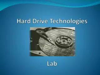
Hard Drive Technologies. Chapter 10. Overview. In this chapter, you will learn how to Explain how hard drives work Identify and explain the PATA and SATA hard drive interfaces Identify and explain the SCSI hard drive interfaces Describe how to protect data with RAID Install hard drives

E N D
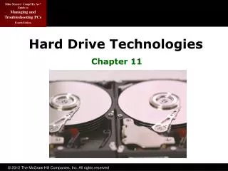
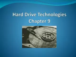
Hard Drive Technologies Chapter 10
Overview • In this chapter, you will learn how to • Explain how hard drives work • Identify and explain the PATA and SATA hard drive interfaces • Identify and explain the SCSI hard drive interfaces • Describe how to protect data with RAID • Install hard drives • Configure CMOS and install drivers
Historical/Conceptual How Hard Drives Work
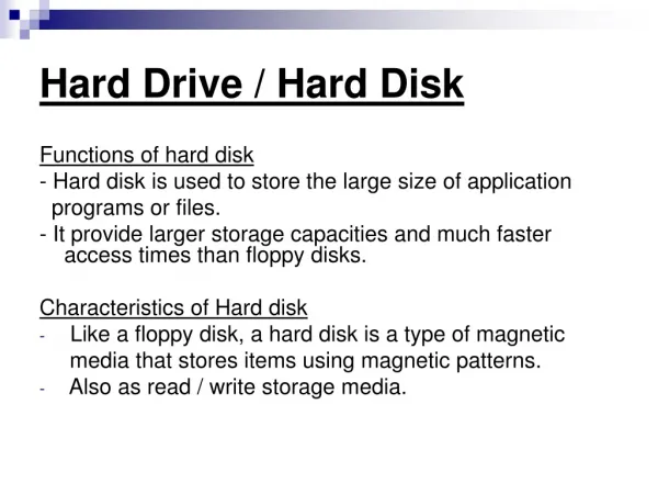
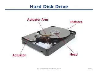
The Platter-based Hard Drive • A traditional hard disk drive (HDD) is composed of individual disks or platters. • The platters are made up of aluminum and coated with a magnetic medium. • Two tiny read/write heads service each platter.
The Platter-based Hard Drive (continued) Figure 1: Inside the hard drive
The Hard Drive • The closer the read/write heads are to the platter, the more densely the data can be packed on to the drive. • Hard drives use a tiny, heavily filtered aperture to equalize the air pressure between the exterior and interior of the hard drive. • Platters spin between 3,500 and 15,000 revolutions per minute (RPM).
The Hard Drive (continued) Figure 2: Read/write heads on actuator arms
Data Encoding • Hard drives store data in tiny magnetic fields called fluxes • The flux switches back and forth through a process called flux reversal • Hard drives read these flux reversals at a very high speed when accessing or writing data • Fluxes in one direction are read as 0 and the other direction as 1
Data Encoding (continued) • Encoding methods used by hard drives are • Run Length Limited (RLL) • Data is stored using “runs” that are unique patterns of ones and zeros • Can have runs of about seven fluxes • Partial Response Maximum Likelihood (PRML) • Uses a powerful, intelligent circuitry to analyze each flux reversal • Can have runs of about 16 to 20 fluxes • Significant increase in capacity (up to 1 TB)
Arm Movement in the Hard Drive • The stepper motor technology and the voice coil technology are used for moving the head actuator • Moves the arms in fixed increments or steps • Only seen in floppies today • The voice coil technology uses a permanent magnet surrounding the coil on the head actuator to move the arm • Automatically parks drive over non-data area when power removed • This is how modern HDDs work
Geometry • Geometry is used to determine the location of the data on the hard drive • CHS (cylinders, heads, sectors) • Used to be critical to know geometry • Had to enter into CMOS manually • Today geometry stored on hard drive • BIOS can query hard drive for geometry data
Heads • Number of read/write heads used by the drive to store data • Two heads per platter (top and bottom) • Most hard drives have an extra head or two for their own usage, so the number may not be even Figure 3: Two heads per platter
Cylinders • Data stored in concentric circles on the platters, called tracks • Cylinders • Group of tracks of the same diameter going completely through the drive Figure 4: Cylinder
Sectors per Track • Number of slices in the hard drive • 512 bytes of storage per sector Figure 5: Sectors per track • Data is stored on the platters in sectors
Obsolete Geometry • Might see in older systems • Write precompensation cylinder • The specific cylinder from where the drive would start writing data farther apart • Internal sectors physically smaller • External sectors physically larger • This identified cylinder where spacing changed • Landing zone • Unused cylinder as “parking place” for heads • Referred to as Lzone, LZ, Park • Needed for older drives using stepper motors
Spindle or (Rotational) Speed • Measured in revolutions per minute (RPM) • The faster the drive, the better the performance • Common speeds: • 5400, 7200, 10,000, and 15,000 RPM • Faster rotational speed produces more heat • Airflow is a key factor in reducing heat • Reduce heat with case fans or bay fans
Spindle or (rotational) speed (continued) Figure 6: Bay fan
Solid-state Drives A solid-state drive (SSD) uses no moving parts Fast Expensive compared to HDDs DRAM- and flash-based drives (latter are more common) Solid-state technology in hard drives, memory cards, and more Figure 7: A solid-state drive (photo courtesy of Corsair)
Flash-based SSDs Pure flash drives for portables Advantages: Very low power usage and heat generation Very fast in reads because no moving parts Extremely rugged—nothing to break Disadvantages Price (as of early 2010) HDDs: $0.10 per GB capacity SSDs: $3.50 per GB capacity Capacity much lower than HDDs, but climbing
Parallel and Serial ATA • ATA interfaces dominate today’s market • Many changes throughout years • Parallel ATA (PATA) historically prominent • Serial ATA (SATA) since 2003 • Called integrated drive electronics (IDE)
Cable Keywords Speed Max Size ATA-1 40-pin PIO and DMA 3.3 MBps to 8.3 MBps 504 MB ATA-2 40-pin EIDEATAPI 11.1 MBps to 16.6 MBps 8.4 GB ATA-3 40-pin S.M.A.R.T. 11.1 MBps to 16.6 MBps 8.4 GB ATA-4 40-pin Ultra 16.7 MBps to 33.3 MBps 8.4 GB INT13 BIOS Upgrade 137 GB ATA-5 40-pin80-wire ATA/33 ATA/66 44.4 MBps to 6.6 MBps 137 GB ATA-6 40-pin80-wire Big Drive 100 MBps 144 PB ATA-7 40-pin80-wire 7-pin ATA/133SATA 133 MBps to 300 MBps 144 PB ATA Overview
ATA-1 • 40-pin ribbon cable • Allowed two drives (one master, one slave) • Programmable I/O (PIO)—traditional data transfer • 3.3 MBps to 8.3 MBps • DMA—direct memory access • 2.1 MBps to 8.3 MBps • Maximum capacity = 504 MB
Early ATA Physical Connections Figure 8: Back of IDE drive showing 40-pin connector (left), jumpers (center), and power connector (right) Figure 9: Relation of drive, controller, and bus
Early ATA Physical Connections (continued) Figure 10: A typical hard drive with directions (top) for setting a jumper (bottom) Figure 11: IDE interfaces on a motherboard
ATA-2 • Commonly called EIDE (Western Digital marketing term) • Increased maximum size to 8.2 GB through LBA and sector translation • Added ATAPI • Could now use CD drives • Added second controller • Added new PIO and DMA modes to increase data transfers to 16.6 MBps
ATA-2 (continued) Figure 12: EIDE drive
Higher Capacity with LBA Figure 13: Too many heads Figure 14: Multiple sectors/track
ATAPI Figure 15: ATAPI CD-RW drive attached to a motherboard via a standard 40-pin ribbon cable Figure 16: Primary and secondary controllers labeled on a motherboard
ATA-3 • Self-Monitoring Analysis and Reporting Technology • S.M.A.R.T. • No real change in other stats
S.M.A.R.T. Information Figure 17: Data Lifeguard Tools Figure 18: S.M.A.R.T. information
ATA-4 • Introduced Ultra DMA Modes • Ultra DMA Mode 0: 16.7 MBps • Ultra DMA Mode 1: 25 MBps • Ultra DMA Mode 2: 33 MBps • These are forms of DMA bus mastering • Ultra DMA Mode 2 also called ATA/33
INT13 Extensions • ATA-1 standard actually written for hard drives up to 137 GB • BIOS limited it to 504 MB due to cylinder, head, and sector maximums • ATA-2 implemented LBA to fool the BIOS, enabling drives up to 8.4 GB • INT13 Extensions extended BIOS commands • Enabled drives up to 137 GB
ATA-5 • Introduced newer Ultra DMA Modes • Ultra DMA Mode 3: 44.4 MBps • Ultra DMA Mode 4: 66.6 MBps • Ultra DMA Mode 4 also called ATA/66 • Used 40-pin cable, but had 80 wires • Blue connector—to controller • Gray connector—slave drive • Black connector—master drive Figure 19: ATA/66 cable
ATA-6 • “Big Drives” introduced (name soon changed to ATA/ATAPI-6) • Replaced INT13 & 24-bit LBA to 48-bit LBA • Increased maximum size to 144 PB • 144,000,000 GB • Introduced Ultra DMA 5 • Ultra DMA Mode 5: 100 MBps (ATA/100) • Used same 40-pin, 80-wire cables as ATA-5
ATA-7 • Introduced Ultra DMA 6 • Ultra DMA Mode 6: 133 MBps (ATA/133) • Used same 40-pin, 80-wire cables as ATA-5 • Didn’t really take off due to SATA’s popularity • Introduced Serial ATA (SATA) • Increased throughput to 150 MBps to 300 MBps
End of PATA Ultra DMA Mode 6 Up to 133 Mbps ATA/133 80-wire cable Problems with PATA Wide, flat cables impede airflow Cable limited to 18” No hot-swapping Reached limits of technology
Serial ATA • Serial ATA (SATA) creates a point-to-point connection between the device and the controller or host bus adapter (HBA) • Narrower cables result in better airflow and cable control in the PC • Maximum cable length of 1 meter • Hot-swappable • No drive limit • Throughput of 150 MBps to 600 MBps Figure 20: SATA hard disk power (left) and data (right) cables
SATA Bridge Figure 21: SATA bridge
AHCI Windows Vista and 7 support Advanced Host Controller Interface (AHCI) Efficient way to work with SATA HBAs Makes hot-swapping work well (otherwise have to run the Add New Hardware Wizard) Native command queuing (NCQ) is a disk-optimization feature that enables faster read/write speeds Implement AHCI in CMOS before installing the OS
SATA Naming SATA drives come in two flavors SATA 1.5Gb SATA 3Gb Marketing hype has branded SATA 3Gb drives as SATA II SATA committee is called the SATA-IO Note the numbers don’t quite add up 1.5 Gb = 192 MBps, not 150 MBps Up to 20 percent lost to overhead and encoding scheme, thus the lower actual speed
External Serial ATA • eSATA • External SATA • Extends SATA bus to external devices • Cable length up to 2 meters • eSATA extends the SATA bus at full speed, which tops out at a theoretical 6 Gbps, whereas the fastest USB connection (USB 3.0, also called SuperSpeed USB) maxes out at 5 Gbps.
External Serial ATA (continued) Figure 23: eSATA ExpressCard Figure 22: eSATA connectors
SCSI • Pronounced “Scuzzy” • Been around since 1970s • Devices can be internal or external • Historically the choice for RAID • Faster than PATA • Could have more than four drives • SATA replacing SCSI in many applications
SCSI Chains • A SCSI chain is a series of SCSI devices working together through a host adapter. • The host adapter is a device that attaches the SCSI chain to the PC. • All SCSI devices are divided into internal and external groups.
SCSI Chains (continued) Figure 24: SCSI host adapter
SCSI Chains (continued) Figure 26: Back of external SCSI device Figure 25: Internal SCSI CD-ROM
Internal Devices • Internal SCSI devices are installed inside the PC and connect to the host adapter through the internal connector. • Internal devices use a 68-pin ribbon cable. • Cables can be connected to multiple devices.
Internal Devices (continued) Figure 28: A 50-pin HD port on SCSI host adapter Figure 27: Typical 68-pin ribbon cable
External Devices • External SCSI devices are connected to external connection of host adapter. • External devices may have two connections in the back to allow for daisy-chaining. • A standard SCSI chain can connect 15 devices, plus the host adapter.