Download

1 / 23
230 likes | 372 Views
SR intelligent controller. SR intelligent controller. 1.General description of SR 2.Features of SR 3.Installation and use of SR software 4. Consultation and service. 1.General description of SR. 1.1 Appearance introduction 1.2 Specifications and type of SR Series

E N D
SR intelligent controller 1.General description of SR 2.Features of SR 3.Installation and use of SR software 4.Consultation and service
1.General description of SR 1.1 Appearance introduction 1.2 Specifications and type of SR Series 1.3 All accessory of SR 1.4 Wiring of SR
1.1 Appearance introduction 1. The structure of SR-12MRAC 1. Input of power supply 2. Input Wiring terminal 3. SR-HMI or SR-WRT 4. LCD display panel 5. Output Wiring terminal size:L*H*D 71*99*55(mm)
2. structure of voice module (SR-VPA/VPD) SR has voice alarm function ,telephone control function and dialing automatically function .to realize these function ,SR should be matched with the SR-VP voice module. 7 6 8 5 4 2 1 3
3. structure of receiver and transmitter Use a wireless transmitter and a receiver to control the ON/OFF status of output of SR.The remote distance can reach 70m. 3 4 5 2 1 6
All accessory Human machine interface SR-HMI Programming panel SR-WRT
All accessory The recording microphone and the wires between the sound card of the PC and the SR-VPA/VPD SR-AUD Communication interface wire between SR and PC SR-CP Lengthened connecting bridge ,to remotely connect the machine and other module SR-ECB
All accessory Remotely connect SR machine and SR-HMI SR-EHC The decorating cover on the SR SR-PC Connecting bridge. To connect the machine and other module SR-CB
All accessory Remote receiving module SR-RCA/RCD Lengthened connecting antenna between SR-RCA and SR-RCD SR-EANT Remote transmitter SR-TC
power Wiring 1. The wiring of SR8 point input and 4 point output Input wiring terminal The maximum output current that can be supplied by SR, is 10A for resistance load and 2A for inductive load output wiring terminal
Wiring 2. The wiring of SR14 point input and 8 point output Input wiring terminal power output wiring terminal
Wiring 3.The D(NPN) transistor output wiring output M Note 1. The “-” terminal of the load power must be connected with the “M” terminal of SR power .a load must be connected with the “+” terminal of the load power 2. The load connecting voltage must be ≤ 80VDC and must be DC
Wiring 4.The GD(PNP) transistor output wiring output L Note • The “+” terminal of the load power must be connected with the “L+” terminal of SR power. a load must be connected with the “-” terminal of the load power • 2. The load connecting voltage must be ≤ 80VDC and must be DC
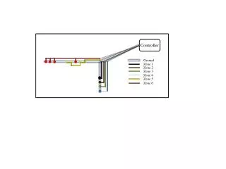
Wiring 5.the connecting diagram of SR and SR-VPA and CP
Features 1. Removable programming panel ( SR-WRT) 2. Flexible human-machine interface (SR-HMI) 3. With the function blocks used for programming ,the program storage capacity of SR is large 4. External extendable input/output 5. Real time clock function 6. Analog input and transmission 7. Security cipher code function 8. Telephone function 9. Wireless control 10. Free programming software (Super CAD)
1. Don’t need additional program implement 3.The timer can be used to setup one year time SR Key Point 1. Comparison with conditional PLC, The superiority of SR 2. it is simple and easy for the learnerto use and master it 2. Comparison with conditional circuit, The superiority of SR 1.Save system connection and debugging time 2.modify circuiteasily maintenance convenience
Super CAD(SR software) 8 basic function module AND Series connection of NO contacts AND +RLO OR Parallel connection of NC contacts (normal close) NAND Parallel connection of NC contacts with RLO borderline test OR Parallel connection of NO contacts NOR Seriesconnection of NC contacts XOR Dual communicator contact NOT phase inverter
Super CAD(SR software) 14 special function module Omnipotence counter Put through postponed Clock switch Cut postponed Simulated compare machine Single impulse relay Impulse relay Timer Order Clock impulse relay Step Order Keep through and postponed Relay Add/Minus Clock RS Relay Time Data compare
Super CAD(SR software) 8 input and output blocks Control in Control out Remote control input dot Telephone module to dial the set telephone and play the set message Voice play module to play the set message Node Connects the two points of the same code and different directions LCD edit Module Double audio frequency pulse