Download
1 / 10
100 likes | 274 Views
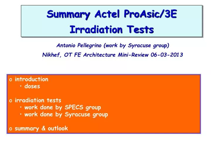
Summary Actel ProAsic /3E Irradiation Tests. Antonio Pellegrino (work by Syracuse group) Nikhef , OT FE Architecture Mini-Review 06-03-2013. introduction doses irradiation tests work done by SPECS group work done by Syracuse group summary & outlook. Radiation Dose estimates.

E N D
Summary ActelProAsic/3E Irradiation Tests Antonio Pellegrino (work by Syracuse group) Nikhef, OT FE Architecture Mini-Review 06-03-2013 • introduction • doses • irradiation tests • work done by SPECS group • work done by Syracuse group • summary & outlook
Radiation Dose estimates Dose per collision (Gy) OT FE Boxes (T1) (see M. Karacson talk at 14 Feb Electronics meeting)
Radiation Dose estimates (cont’d) (see M. Karacson talk at 14 Feb Electronics meeting) At FE location of T3 : ~210-14 Gray per collision Assume (el+inel = 72 mb)0.721014 collisions per fb-1 N(L,el+inel) = L·el+inel N(1fb-1,72mb) = 1015b-1·7210-3 b = 0.721014 At FE location of T3 : ~1.44Gray (0.144 krad) per fb-1 e.g. ~7.2 krad for 50 fb-1 Adopting a factor 2 safety for the simulation uncertainty and another factor 2 safety for the FE irradiation tests a good figure to remember as radiation-hardness specification is ~30 krad to get the feeling… http://lhc-statistics.web.cern.ch/LHC-Statistics/ : 73d,17h,45m stable-beam 2012LHC~0.637107s L(1yLHC,101032 cm-2s-1) = 0.637107s · 103310-24 b-1s-1= 6.37 fb-1
A word about FPGA’s Heidelberg design based on: ALTERA ARRIA GX FPGA 35K 780FBGA (EP1AGX35DF780I6) • 90-nm process technology (Arria II family 40-nm) • based on technology of Altera'sStratix® II GX FPGA Nikhef design based on: Actel ProAsic3/E A3PE1500 (A3PE1500-2FGG484) • 130-nm process technology • based on nonvolatile flash technology Background consideration: nonvolatile flash technology should be more radiation-tolerant (also already experience with SPECS and TFC-FAN FPGAs in CtrlBox). However, processes that combine Flash and CMOS are typically 2-3 generations behind leading-edge CMOS processes used by SRAM-based FPGAs. Irradiation Tests mandatory!
Irradiation Tests Actel ProAsic3E • SPECS project testedProasicalready in 2004 (SPECS + TFC-fan in CtrlBox) (D. Breton, J. Lefrançois et al., unpublished) • programmable up to ~17 krad • stillfunctioninguntil ~30 krad, then high current and malfunction Tests of 3APE1500(-2) in 2010-2012 with 200Mev protons at Boston hospital (Syracuse University, M. Artuso, E. Cowan, Bin Gui, D. Hsu, R. Mountain, JC Wang) • see talk by R. Mountain in LHCbElectronis Upgrade Meeting 14/Oct/2010 • see talk by R. Mountain in LHCbElectronis Upgrade Meeting 21/Jul/2011 • roughlyreproduceresultsfrom SPECS test • RAM: few SEU every 3min run (few krad per run) • similarlyfor Flash ROM • see talk byJC Wang in LHCb Electronics Upgrade Meeting 14/Feb/2012 • dedicated test of PLL and Nikhef TDC firmware (see next slides)
Actel Tests – People & Setup ~28 mm (package) Proton Radio-Chromatograph Front Back Relative Flux Position (cm) Alignment Laser spot • 226 MeV proton beam • test 2 Actel’s at a time “back” 68% radiation of “front”
Actel PLL & TDC Test Setup (Nikhef + Syracuse) Twisted pair cable provides delay for TDC to measure Check if frequencies of produced clocks are correct Measure 40 MHz time signal, with 1280 MHz equivalent precision. Record during 3min (233 BX’s) runs (~2 krad) Generate two 320 MHz and one 80 MHz clocks of fixed phases Set a 5-bit number for comparator to check against measured TDC Check if measured TDC value agrees with U13/14
Irradiation Dose Actel PLL & TDC talk byJC Wang in LHCb Electronics Upgrade Meeting 14/Feb/2012 Chips are tested in pairs FPGA 4 (front) & FPGA 3 (back) FPGA 2 (front) & FPGA 1 (back) FPGA J (front) & FPGA L (back) Dose(back) ~ 68% Dose(front) All FPGAs receives 30 kRad or more, except for FPGA 1 that was intentionally removed for other tests
Irradiation Results Actel PLL & TDC talk byJC Wang in LHCb Electronics Upgrade Meeting 14/Feb/2012 Verification failed Reconfiguration failed x3 Power-cycle reconfiguration failed Results for FPGA 2 (received 45.6 krad) PLL lock error. (run was with high intensity) Verification OK Reconfiguration OK Verification OK Change comparator value to 11: large error count is seen. Change back to 10. Near station Computer crashed LED indicates TDC = 12 1.2x10⁹ 38 1 37
Summary irradiation tests Actel talk by R. Mountain in LHCbElectronis Upgrade Meeting 14/Oct/2010 talk by R. Mountain in LHCbElectronis Upgrade Meeting 21/Jul/2011 talk byJC Wang in LHCb Electronics Upgrade Meeting 14/Feb/2012 Preliminary • programmable up to ~17 krad • stillfunctioninguntil ~30 krad, then high current and malfunction • RAM: few SEU every 3min run (few krad per run) • afterirradiation, all chips failfirmwareverification and reconfiguration • buttheystillseem to function as TDC’s • hardlyany PLL lock lost • few TDC errors up to ~30 krad, then TDC valuesseem to “shift” Write-up with final analysis forthcoming Major thanks to Erika, Marina, Bin, Dylan, JC, Ray etc. Actel kind of “passes” the tests, but margin quite narrow... (future generation from Microsemi 100 krad TID in 65-nm tech?) (if enough manpower at Nikhef, also looking at SMARTFUSION2, IGLOO2)