Download
1 / 16
160 likes | 161 Views
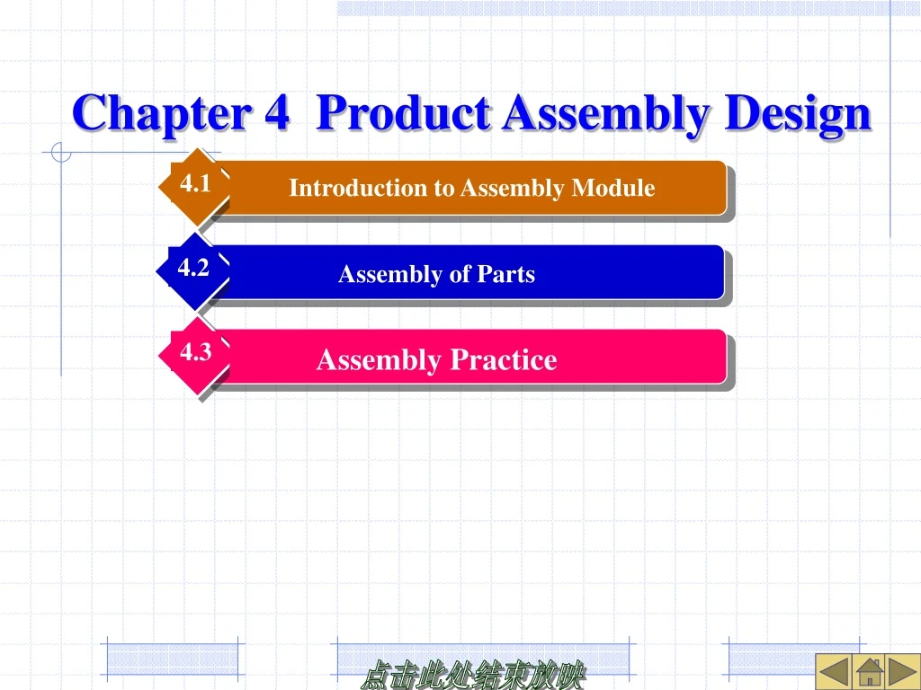
4.1. 4.2. 4.3. Introduction to Assembly Module. Assembly Practice. Assembly of Parts. Chapter 4 Product A ssembly D esign. 4.1 Introduction to Assembly Module.

E N D
4.1 4.2 4.3 Introduction to Assembly Module Assembly Practice Assembly of Parts Chapter 4 Product Assembly Design
4.1 Introduction to Assembly Module In product design, assembly modules can be used to place or create assembly components, or to modify assembly properties to meet certain design requirements. Because Pro / E uses a single database technology, the components in the assembly module still maintain the relationship with their parts files. No matter which party's dimension parameter value changes, the parameter value related to it must also change accordingly. When the assembly is saved, each component created will be saved as a separate part file and allowed to be modified in part mode.
4.1.1Assembly Mode Startup and Environment New file: Assembly, Subtype: Design. Interface of component mode: two new icon buttons are added to the right feature toolbar. Buttons are used to assemble components in the assembly; Buttons are used to create components directly in the assembly environment. Figure 9-1 Assembly mode startup and environment
4.1.2 Two Basic Methods of Component Design Bottom - up assembly design: in assembly mode, the created parts or subassemblies are placed together according to their mating relationship to form a new assembly, that is, the process of assembling components. Select [Insert] → [Component] → [Assembly] command, or click the feature tool button. Top - down assembly design: the process of directly creating assembly components in assembly mode, that is, creating components. Select [Insert] → [Component] → [Create] command, or click the feature tool button. Applications: The former is often used in occasions where the product assembly relationship is clear or the part shape is standardized. The latter is mostly used in real product design, i.e. first determine the outline of the product, then gradually refine the product design until it is refined to a single part.
4.2 Assembly of Parts • Click the button in the feature toolbar to create an assembly by specifying the assembly constraint relationship between related assembly components and directly placing existing parts or subassemblies. This assembly design method is called bottom-up assembly design. At this point, the target file associated with the placed component is transferred to the memory of the Pro / E system. When you open an assembly file, individual components associated with it cannot be purged from memory. • When assembling a component, the most important step is to use constraints to specify how and where the component is placed relative to the assembly. Pro / E provides a variety of constraint types to achieve component positioning. Constrain types Match Automatic Figure 9-2 Type of assembly constrains
4.2.1 Assembly Constraint Type • 1.Mate: Used to position two planes facing each other. • There are three types of offsets available: Coincident, Orient, and Offset. Offset Figure 9-4 Assembly constrain of mate coincident Figure 9-3 Assembly constrain of offset type Figure 9-5 Matching constraint of offset type
4.2.1 Assembly Constraint Type • 2.Align: Used to position the two planes in the same position and in the same direction, or make the two axes collinear and coincident. • There are three types of offsets available: Coincident, Orient, and Offset. When using multi-axis or multi-point alignment constraints, there are two situations, mandatory or non - mandatory. Figure 9-6 Alignment constraints for coincident Figure 9-7 Alignment constraints for directional types Figure 9-8 Forced constrain
4.2.1 Assembly Constraint Relation • 3. Insert:Insert the rotating surface of the component into the rotating surface of the assembly (i.e., coaxial constraint). When defining,it is required to select the surface of the rotating feature. • 4. Coord SYS: Used to align the assembly coordinate system with the component coordinate system, when the corresponding axes of the two coordinate systems are aligned with each other. Figure 9-9 Insertion constrain Figure 9-10 Coordination constrain
4.2.1 Assembly Constraint Relation • 5. Tangent: Used to position the two surfaces in a tangent state at the contact point and facing each other. • 6. Point on Line: Used to define the alignment of vertices or datum points on the component to be assembled with existing edges, datum curves or axes in the assembly model. Figure 9-11 Tangency constrain Figure 9-12 Point on line constrain
4.2.1 Assembly Constraint Relationship • 7. Point on Surface: Used to define that the vertex or datum point on the component to be assembled is aligned with the surface or datum plane of the assembly model. • 8. Edge on Surface: Used to define that an edge on the component to be assembled is aligned with a surface of the assembly model. • 9. Automatic: The system automatically sets appropriate constraints according to the characteristics of the assembly components. • Default: Assemble in the system preset way so that the coordinate system of the transferred-in component is aligned with the default coordinate system of the assembly model; Fixed: Fixes the moved or packaged component to its current position. Figure 9-14 Line constraints on surfaces Figure 9-13 Point constraints on surfaces
4.2.2 Assembly Constraint Relation When adding a component, select the [Insert] → [Component]→ [Assembly] command or click the button ,then select the required part file, and the system displays the component placement dashboard. In the component placement dashboard, you can define the constraint relationship for placing components in the assembly model. and buttons are used to set the placement of the components to be transferred in the assembly model. The former means that when defining assembly constraints, the transferred-in components are displayed separately in a small window. The latter indicates that the imported component is displayed in the assembly graphics window and the component position is updated when the constraint is defined. Status: partial constrained Move Property Place User defined Match Change of constrain direction Show place status Separate window button Place component List of offset types List of constrains List of predefined sets Switch between user defined sets or predefined sets Component windows button Place components manually Figure 9-15 Component place control panel
4.2.2 General Steps for Assembly of Parts 1. Component Placement Dashboard ( 1 ) " Place" slide - up panel: Establish assembly constraint relationship between components. User Defined Sets List Box: Display and define constraints and their references. Constraint Type List Box: Display and specify the constraint type of the component, which reverses the constraint direction of the component. Offset List Box: Specify the type of offset that matches or aligns the constraint. ( 2 ) " Move" slide - up panel: Move and place the currently active assembly component, but only within the degree of freedom defined by existing constraints. Four types of motion are supported, namely, Orient Mode, Translate, Rotate, and Adjust. Figure 9-17 Move panel Figure 9-16 Place panel
4.2.2 General Steps for Assembly of Parts 2. The steps of parts assembly ( 1 ) Select [Insert] → [ Component ] → [ Assembly ]. ( 2 ) Select the components (or subassemblies) to be assembled. ( 3 ) Set the component to be displayed in a separate window or component graphics window (default). ( 4 ) Define placement constraint types for placement components and assemblies and select references. ( 5 ) According to the need of constraint type, select offset type and set offset value. ( 6 ) The system automatically activates a new constraint until the component is fully constrained. ( 7 ) Click the middle mouse button to place the component under the current constraint.
4.2.4 Editing Assemblies and Components Right - click a component in the model tree and edit it with the shortcut menu command, or through the [Edit] → [Component Operations] command. 1. Operation of assembling components It is allowed to modify the design of components in various ways, such as deleting, hiding, editing definitions, etc. 2. Modify the part size and features After you activate a component in the assembly environment, you can add or redefine features, edit relationships, and so on. When an assembly component is activated, other inactive components will be grayed out and transparently displayed in shaded mode. Edit, hide, and information operations can only be performed on inactive components in an assembly. After the component is activated, two operations are allowed: modifying feature sizes and adding various types of features. Menu Manager Figure 9-21 Right click shortcut menu Figure 9-22 Component operation command Figure 9-23 Inactive component colored display
4.2.4 Editing Assemblies and Components 3. Change of assembly structure Use [ Rebuild ] to move parts from a top-level assembly at a higher level to a subassembly at a lower level, or from one subassembly to another, and vice versa. [Rebuild] is aimed at readjusting the product structure of the completed assembly. The following considerations should be taken into account when performing a rebuild: (1) You cannot select a subassembly or the first component of an assembly. (2) When the original component and the target component are members of the same level of assembly, the sub-item of the original component must be transferred at the same time. (3) Components belonging to an array cannot be reconstructed. (4) When an assembly contains multiple copies of the same subassembly, the components of the subassembly cannot be rebuilt. (5) When the original component appears many times, the component cannot be rebuilt. Figure 9-24 Restructure menu Figure 9-25 Assembly structure before change Figure 9-26 Assembly structure after change
4.2.4 Editing Assemblies and Components 4. Regeneration of Parts and Assemblies ( 1 ) Regenerate all changed parts Right - click the component in the model tree and select Regenerate from the shortcut menu or click the button . If a composite feature is added to the component, the " Confirm Update" dialog box will be displayed. ( 2 ) Customized regeneration After the feature is changed in the component, the custom regeneration can be started by clicking the button or selecting the [Edit] → [Custom Regenerate] command. Right-click the component in the model tree and select [Custom Regeneration] from the shortcut menu. Click the icon in the lower right corner of the status bar. After the customized regeneration is started, the Regeneration Manager dialog box will be displayed. Figure 9-27 Confirm dialog box Figure 9-27 Regenerate dialog box