Download
1 / 47
470 likes | 586 Views
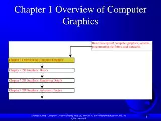
Chapter 2. Overview of Graphics System. Video Display Devices. primary output device : video monitor (based on cathode-ray tube, CRT 음극선관 혹은 브라운관 ) Refresh Cathode-Ray Tubes basic operation of a CRT ( 그림 2-2)

E N D
Chapter 2. Overview of Graphics System Chapter 2. Overview of Graphics Systems
Video Display Devices • primary output device : video monitor (based on cathode-ray tube, CRT 음극선관 혹은 브라운관) • Refresh Cathode-Ray Tubes • basic operation of a CRT (그림2-2) • electron gun에 의해 방출되는 전자파 (a beam of electrons, 즉 cathode rays)가 focusing systems와 deflection systems를 통과하여 형광체로 입혀진 스크린을 향한다. • 형광체는 전자파가 접촉하는 지점에 작은 빛을 방사한다. • 형광체에 의해 방사되는 빛은 즉시 흐려져가기 때문에 스크린 픽춰를 유지하기위한 방법이 필요하다. • 한 방법으로 같은 지점에 전자파가 향하도록 반복적으로 그림을 그리는 것으로 이러한 타입의 디스플레이를 refresh CRT라고 함 Chapter 2. Overview of Graphics Systems
Figure 2.2 Basic design of a magnetic deflection CRT Chapter 2. Overview of Graphics Systems
CRT 구성 요소(그림 2-3) • heated metal cathode, a control grid, heating filament, focusing anode, accelerating anode • 필라멘트에 전류가 흐르면서 열이 음극(cathode)에 가해짐으로써 전자가 뜨거운 음극 표면으로부터 떨어져 나오게 된다. • CRT내부의 진공관에서 마이너스로 충전된 전자들이 high positive voltage로 덮힌 형광체를 향하여 가속화된다. • 가속화시키는 전압은 스크린 가까이의 CRT 내부에 플러스로 충전된 금속에 의해 생성되거나 아니면 가속화시키는 양극(accelerating anode)에 의해 생성되기도 한다. • 전자파의 강도는 control grid의 voltage level를 세트하여 조절된다. • focusing systems의 역할: 전자파가 형광체에 부딪히는 한 점에 모아지도록 하는데 쓰임. focusing은 전장 (electric field) 이나 자장 (magnetic field)에 의해 이루어짐 • electrostatic (정전기) focusing : TV나 그래픽스 모니터에 잘 이용됨: 전자파가 스크린의 중앙에 모아지도록 하는 것 Chapter 2. Overview of Graphics Systems
Deflection of electron beam: electric field or magnetic field에 의해 조절 • two pairs of magnetic deflection coils 이용 • 각각 horizontal deflection, vertical deflection에 이용됨 • deflection의 양은 코일을 흐르는 전류에 의해 조정됨 • 스크린 위에 빛 생성은 CRT 전파 에너지가 형광체에 전달됨으로써 이루어짐. • CRT에 이용되는 형광체는 color 외에 persistence (지속성, CRT beam이 제거되고 나서 얼마동안 빛을 발하느냐)에 따라 여러 종류가 쓰여지고 있다. Chapter 2. Overview of Graphics Systems
Figure 2-3 Operation of an electron gun with an accelerating anode Chapter 2. Overview of Graphics Systems
resolution : CRT내에 중복없이 가장 많이 디스플레이 될 수 있는 점의 수 • CRT의 resolution은 형광체의 타입, 디스플레이되는 빛의 강도, focusing and deflecting systems에 따라 다르다. • high-quality system의 전형적인 resolution은 1280 by 1024 • 그래픽스 모니터의 physical size는 스크린의 대각선의 길이로 12인치에서 27인치 혹은 그이상 • 비디오 모니터의 또 하나의 성질로 aspect ratio가 있음 • vertical points와 horizontal points의 비율을 말함 (vertical points / horizontal points) : 스크린에 양방향으로 같은 길이의 라인을 생성해 내는데 필요한 수직점과 수평점의 비율로 aspect ratio가 3 / 4는 3개의 점으로 구분된 수직선과 점 4개로 구분된 수평선이 같은 길이를 갖는 것을 말함 Chapter 2. Overview of Graphics Systems
Raster Scan Displays • CRT를 이용한 가장 일반적인 형태의 그래픽스 모니터, 텔레비젼 기술을 근거로 함 • 전자광선 (electron beam)이 위에서부터 아래로 한줄씩 스크린을 지나가면서 광선의 강도가 켜졌다 꺼졌다하면서 빛나는 점의 형태를 생성 • 그림의 정의는 refresh buffer 혹은 frame buffer라고 불리우는 메모리에 저장됨. 이 메모리는 스크린의 모든 점들에 대한 빛의 강도 (intensity values)를 가지고 있다. 이 저장된 값들이 frame buffer로부터 꺼내져 한번에 스크린에 한줄씩 (scan line) 그려지게 된다. • 스크린의 각 포인트를 pixel 혹은 pel (picture element)이라고 불림 • black and white system에선 각 스크린 포인터가 on/off이면 되므로 픽셀당 1비트가 필요하게 되며, 칼라나 빛의 강도에 변화를 주기위해선 픽셀당 비트수가 추가적으로 필요하다. 픽셀당 24비트로 스크린 해상도 (resolution)이 1024 by 1024의 경우인 시스템은 frame buffer의 크기가 3 megabytes를 필요로 한다. Chapter 2. Overview of Graphics Systems
some raster-scan systems에서는 각 프레임이 interlaced refresh procedure를 이용한 two passes로 디스플레이된다. • first pass에서는 광선이 위에서부터 아래로 한 줄 건너서 지나가고 난 뒤에 vertical retrace (한 프레임의 끝에서 다음 프레임을 시작하기 위해 스크린의 top left corner로 가는 것, horizontal retrace는 전자광선이 다음 스캔라인을 디스플레이하기 위해 스크린의 left side로 가는 것을 말함) 후에 광선은 남아있는 스캔라인을 지나간다. • 위에서부터 아래까지 모든 라인을 지나가는데 걸리는 시간의 반으로 전체 스크린이 디스플레이된다. • 초당 30프레임의 noninterlaced display의 경우 flicker현상이 발생하나 interlacing으로 초당 60프레임에 가까운 refresh rate를 가져오므로 flicker를 피할 수 있는 효과가 있다. Chapter 2. Overview of Graphics Systems
Random Scan Displays • random-scan display unit의 경우엔 CRT가 스크린에서 그림이 그려질 부분으로만 전자광선이 향하도록 되어 있다. • random-scan monitor는 한번에 한 라인씩 그림을 그리기 때문에 vector displays, stroke-writing displays, calligraphic displays라고 불리운다. • 한 물체의 구성인 선분들을 지정된 어떤 순서대로라도 그릴 수 있다. • pen plotter도 이와 비슷하게 작동하며 random-scan, hard-copy device의 일종 • picture definition은 refresh display file(display list, display program, refresh buffer라고도 함)에 line-drawing commands로서 저장됨 • line-drawing applications를 위해 설계되었으며 realistic shaded scenes의 경우는 디스플레이 할 수 없슴 • picture definition이 모든 스크린 포인트에 대한 intensity values가 아니라 line-drawing instructions로 저장되어 있기 때문에 raster systems보다는 high resolution을 갖는다. • raster systems이 jagged lines으로 표시되는 반면, vector displays는 smooth line drawing를 디스플레이한다. Chapter 2. Overview of Graphics Systems
Color CRT Monitors • CRT monitor는 여러 다른 색의 빛을 방출하는 형광체의 조합으로 color pictures를 디스플레이한다. • two basic techniques • beam-penetration method • random-scan monitor에 이용됨 • red, green의 두 층의 형광체가 스크린 안쪽에 덮여져 있음 • 색은 electron beam이 형광체의 층으로 얼마만큼 멀리 들어가느냐로 나타내진다. • slow electron beam은 out red layer만 자극시키고 fast electron beam은 inner green layer를 자극시킨다. 중간속도의 electron beam은 orange와 yellow를 보여준다. • electron의 속도는 beam-acceleration voltage로 조절된다. Chapter 2. Overview of Graphics Systems
shadow-mask method • color TV를 포함하는 raster-scan systems에 이용 • beam penetration method보다는 광범위의 color를 생성 • shadow-mask CRT는 각 픽셀 위치에 형광체가 3가지 색의 점을 가짐 • 각각이 R, G, B의 빛을 발함 • CRT가 three electron guns (각 color dot에 대해 하나씩 존재)와 형광체로 덮힌 스크린 바로 뒤에 shadow-mask grid가 있다. • delta-delta shadow-mask method: color CRT systems에 많이 쓰이는 방법 (그림2-10) • three electron beams가 shadow mask의 구멍을 통해 스크린상의 small dot triangle로 나타냄 • in-line arrangement 방법 • 삼각형의 패턴이 아니라 하나의 스캔라인으로 정렬되어 high-resolution color CRT에 이용됨 Chapter 2. Overview of Graphics Systems
Figure 2-10 Operation of a delta-delta, shadow-mask CRT Chapter 2. Overview of Graphics Systems
three electron beams의 intensity levels를 변화시켜 color variation 형성 • white or gray : all three dots에 같은 강도를 주었을 때 • yellow : green and red dots만으로 생성 • magenta : blue and red dots로 생성 • cyan: blue and green으로 생성 • 그래픽스 시스템의 color CRT는 RGB monitor로서 설계됨 • shadow mask를 이용하고 컴퓨터로부터 직접 각 electron gun의 intensity level을 얻음 • high-quality raster-graphics systems는 frame buffer에 픽셀당 24비트를 가지고 픽셀당 17 million color choices 를 허용 - full-color system or true-color system이라고 함 - 224 = 210 * 210 * 24 = 약 1700만 칼라 Chapter 2. Overview of Graphics Systems
Direct View Storage Tubes (DVST) • 스크린 이미지를 유지는 다른 방법으로 CRT내부에 picture information을 저장 • 형광체로 덮힌 스크린 바로 뒤에 picture information 저장 • two electron guns 이용: primary gun은 picture pattern을 저장하는데 이용되고, secondary gun은 picture display를 유지시키는데 이용됨 • 장점: refreshing이 필요없으므로 복잡한 그림을 flicker없는 high-resolution 으로 디스플레이 • 단점: 색을 디스플레이 하지 않으며 그림의 일부분을 제거할 수 없으므로, 전체 스크린을 제거하고 그림을 새로 그려야 함 - 복잡한 그림일 경우에 시간이 많이 걸림 Chapter 2. Overview of Graphics Systems
Flat Panel Displays • CRT에 비해 reduced volume, weight, and power requirements를 갖는 비디오 디바이스를 말함 • 현재, TV monitors, calculators, pocket video games, laptop computers등에 이용되고 있음 • two categories • emissive displays (emitters) - electrical energy를 빛으로 변환 • plasma panel (gas-discharge displays) • thin-film electroluminescent displays • light-emitting diodes (LED) 등 세가지 타입이 있슴 • nonemissive displays - 빛을 그래픽 패턴으로 바꿈 • liquid-crystal device가 대표적 예: calculator, portable laptop computer • 현재는 "작은” 시스템은 아님 Chapter 2. Overview of Graphics Systems
Three Dimensional Viewing Devices • 3차원 scene의 디스플레이를 위한 그래픽스 모니터는 CRT 이미지를 진동하며 굴절성인 거울로 반사하는 기술로 고안됨 • 다양한 촛점을 갖는 거울이 진동하면 초점거리가 변하며 이러한 진동에 의해 CRT위에 물체가 표현됨 Chapter 2. Overview of Graphics Systems
Stereo and Virtual Systems • true three dimensional images를 생성하는 것이 아니고 관측자의 눈에 물체의 depth를 보이게 하는 three-dimensional effect 를 제공하는 방법 • stereoscopic projection을 위해선 한 scene에 대해 two views를 구해야 됨 (left and right eye의 viewing direction으로부터) • stereoscopic effect 생성의 한 방법으로 two views를 alternate refresh cycles로 표현함 • stereoscopic viewing은 가상현실 시스템 (유저가 scene으로 들어가 그 환경과 서로 상호작용 함) 의 구성요소가 됨 • headset: stereoscopic views를 생성함 Chapter 2. Overview of Graphics Systems
Raster Scan Systems • raster : 브라운관에 비치는 가는 가로줄 무늬 • organization of raster systems (그림2-24) • CPU, video controller (display controller), frame buffer (system memory) • video controller • frame buffer memory를 direct access • frame buffer locations와 이것에 대응하는 스크린 위치는 Cartisian 좌표를 취한다. 대부분, 원점이 스크린의 lower left corner로 정의됨 • 스크린이 2차원 시스템의 1/4을 나타내며 오른쪽으로는 x값이 positive로 변하고 y값은 밑에서 부터 위로 가면서 positive하게 바뀐다. (시스템에 따라 upper left corner가 원점인 경우도 있음) • basic refresh operations of video controller (그림2-27) • two registers: 스크린 픽셀의 좌표치를 저장 • x-register는 0, y-register는 ymax에서 시작한다. • frame buffer에서 이 픽셀 위치의 값을 꺼내어 CRT beam의 intensity로 함 • CRT beam intensity를 직접 조정하지 않고 lookup table을 이용하는 경우도 있음 Chapter 2. Overview of Graphics Systems
Figure 2-24 Architecture of a simple raster-graphics system Chapter 2. Overview of Graphics Systems
Figure 2-25 Architecture of a raster system Chapter 2. Overview of Graphics Systems
Figure 2-26 A Cartesian reference frame with origin Chapter 2. Overview of Graphics Systems
Figure 2-27 Basic video-controller refresh operations Chapter 2. Overview of Graphics Systems
Raster scan display processor (그림2-28) • 별도의 display processor (graphics controller)를 갖는 raster system 구성 • major task: 그림의 정의를 digitize해서 frame buffer에 저장할 pixel-intensity value를 구하는 작업 -> scan conversion이라고 함 • 예를 들어 line segment를 scan conversion 하는 것은 line path에 근접한 픽셀의 위치를 정하고 그것의 intensity value를 frame buffer에 저장하는 것이다. Chapter 2. Overview of Graphics Systems
Figure 2-28 Architecture of a raster-graphics system with a display processor Chapter 2. Overview of Graphics Systems
Graphics Monitors and Workstations • 그래픽스 시스템은 small general-purpose compute systems로부터 복잡한 full-color 시스템에 이르기까지 광범위하다. • diagonal screen dimensions for general-purpose personal computers : 12 to 21 inches, 16 to 32000 color range • 워크스테이션의 경우 스크린 해상도가 1280 x 1024가 전형적이며 screen diagonal은 16인치 이상, 8-24 bits per pixel Chapter 2. Overview of Graphics Systems
Input Devices • Keyboards • entering text strings, picture labels, screen coordinates, menu selections, graphics function 입력시 사용 • cursor-control keys, function keys사용 • button box, input dial, 스위치 등을 사용하기도 함 : data value or customized graphics operation을 선택할 때 • Mouse • trackball and spaceball • 스크린 커서의 이동 • trackball: two dimensional positioning device • spaceball: six degrees of freedom 제공 • Joysticks • 스틱이 중앙에서 어떤 방향으로 움직인 거리가 스크린 커서의 이동을 의미 Chapter 2. Overview of Graphics Systems
Figure 2-43 A movable joystick Chapter 2. Overview of Graphics Systems
Data glove • 손과 손가락의 움직임을 탐지하기 위한 센서로 구성됨 • two-dimensional projection은 비디오 모니터로 보고 three-dimensional projection은 headset로 볼 수 있다. • Digitizer • drawing, painting, interactively selecting coordinate positions • graphics tablet: input two-dimensional coordinates • electromagnetic (전자기) resonance (공명) 이용 • hand cursor 혹은 stylus로 입력 • three dimensional digitizer: sonic (음향) or electromagnetic (전자기) transmission 이용 • Image scanner • 그림을 이미지스캐너에 의해 내부 표현으로 바꾼 뒤에는 rotate, scale, crop 등 여러가지 변형을 줄 수 있다 -> 이미지 처리 Chapter 2. Overview of Graphics Systems
Figure 2-44 A virtual reality scene, displayed on a two-dimensional video monitor Chapter 2. Overview of Graphics Systems
Figure 2-45 The SummerSketch III desktop tablet Chapter 2. Overview of Graphics Systems
Figure 2-46 The Microgrid III tablet with sixteen-button hand cursor Chapter 2. Overview of Graphics Systems
Figure 2-49 A three-dimensional digitizing system Chapter 2. Overview of Graphics Systems
Touch panel • 오브젝트나 스크린 위치 선택이 손의 접촉에 의해 이루어짐 • 터치스크린으로도 이용 • input은 optical, electrical, acoustical (음향) 방법 이용 • optical touch panel: 적외선의 LED (light-emitting diodes)이용 • electrical touch panel: 약간 떨어져 있는 두개의 투명판 (양극) 으로 구성, 하나는 전도체로 덮혀있고 다른 하나는 저항체로 덮혀져 있슴 • acoustical touch panel : 유리판에 수평, 수직방향으로 고주파의 음파가 생성 • Light pen • 스크린에 펜의 구멍으로부터 나온 빛으로 스크린의 위치를 선택 • 단점 : light pen으로 스크린을 가리키기 때문에 그림의 일부가 가리게 되고 어두운 지역은 탐지되지 않는다. 픽셀값이 Nonzero intensity를 가져야 한다. Chapter 2. Overview of Graphics Systems
Figure 2-55 A light pen with a button Chapter 2. Overview of Graphics Systems
Voice systems • 미리 정의된 단어, 구 등과 매칭시켜 입력됨, 사전을 미리 준비하여야 함 • speech recognition system에 의해 음성과 사전을 매칭시킴 • 오퍼레이터가 여러 디바이스에 신경쓰지 않아도 되는 장점이 있슴 Chapter 2. Overview of Graphics Systems
Hard Copy Devices • 프린터 혹은 플로터로 그래픽스 이미지를 출력 • 그림의 질은 dot size, number of dots per inch, lines per inch에 따라 다름 • 프린터 출력 방법으로 • impact (충돌) printer: formed character를 inked ribbon을 통해 종이에 프린트 • 라인 프린터가 예 • nonimpact printer: laser technique, ink-jet spray, xerographics (xero- 건조) processes, electrostatic method, electrothermal (전열) methods 등 이용 Chapter 2. Overview of Graphics Systems
Graphics Software • 그래픽스 소프트웨어의 두 가지 종류 • general programming packages • C 나 FORTRAN같은 high-level language에서 이용되는 그래픽스 함수를 제공 • 예를 들어 Silicon Graphics의 GL (Graphics Library) • picture components (straight lines, polygons, circles 등) 생성, color나 intensity value 지정, views의 선택 및 변환 수행 • special-purpose applications packages • nonprogrammer들을 위한 것 • 예를 들어 painting programs, CAD systems 등 Chapter 2. Overview of Graphics Systems
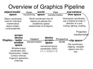
Coordinate Representations • 일반적인 그래픽스 패키지는 Cartesian coordinate specifications을 이용 • 물체를 화면에 나타내기 위한 일련의 과정 (그림2-60) • modeling coordinates • world coordinates • normalized coordinates • device coordinates Chapter 2. Overview of Graphics Systems
Figure 2-60 The transformation sequence from modeling coordinates to device coordinates for a three-dimensional scene Chapter 2. Overview of Graphics Systems
Graphics functions • general-purpose graphics package는 그림을 생성하거나 조작하기위한 여러 함수를 제공 • input, output, attributes, transformations, viewing or general control • basic building block : output primitives라고 함 • character strings and geometric entities (points, straight lines, curved lines, filled areas and shapes defined with arrays of color points) 포함 • 그래픽스 함수의 기능 • attributes: output primitives의 성질 • intensity, color, line styles, text styles, area-filling patterns • geometric transformations 혹은 modeling transformations에 의해 • 물체의 크기, 위치, 방향을 변환 • viewing transformations • 디스플레이될 영역의 시야를 정의함 Chapter 2. Overview of Graphics Systems
그림은 여러 structures (segments or objects)로 나누어 구성되고 각 structure에 대해 creation, modification, transformation 수행 • Input functions • mouse, tablet, joystick과 같은 input device를 컨트롤 • control operations • clearing a display screen, initializing parameters와 같은 기능 수행 Chapter 2. Overview of Graphics Systems
Software Standards • 목적 : portability • International and national standards planning organizations에 의해 • GKS (Graphical Kernel System)가 개발되고 ISO (International Standards Organization), ANSI(American National Standards Institute) 등에 의해 첫번째 그래픽스 소프트웨어 표준으로 채택됨 • PHIGS (Programmer’s Hierarchical Interactive Graphics Standard) • GKS의 확장 • 프로그래밍언어에 독립적인 표준 그래픽스 함수 제공 • 예) PHIGS나 GKS에서 n-1개의 선분 연결은 • polyline(n, x, y) • language binding도 제공되고 있슴 • standard for storing and transmitting pictures : • CGI (Computer Graphics Interface) : device interface methods를 위한 표준 • CGM (Computer Graphics Metafile) : 그림 기록 혹은 이송과 관련된 표준 Chapter 2. Overview of Graphics Systems
OpenGL 예제 # include <GL/glut.h> void init (void) { glClearColor (1.0, 1.0, 1.0, 0.0); // Set display-window color to white glMatrixMode (GL_PROJECTION); // Set projection parameters gluOrtho2D (0.0, 200.0, 0.0, 150.0); } void linesegment(void) { glClear (GL_COLOR_BUFFER_BIT); // Clear display window glColor3f (1.0, 0.0, 0.0); // Set line segment color to red glBegin (GL_LINES); glVertex2i (180, 15); glVertex2i (10, 145); glEnd ( ); } Chapter 2. Overview of Graphics Systems
void main (int argc, char** argv) { glutInit (&argc, argv); // Initialize GLUT. glutInitDisplayMode (GLUT_SINGLE | GLUT_RGB); // Set display mode glutInitWindowPosition (50, 100); // Set top-left display-window position glutInitWindowSize (400, 300); // Set display-window width and height glutCreateWindow (“An Example OpenGL Program”); init( ); // Execute initialization procedure glutDisplayFunc (linesegment); // Send graphics to display window glutMainLoop ( ); // Display everything and wait } Chapter 2. Overview of Graphics Systems
Figure 2-61 A 400 by 300 display window Chapter 2. Overview of Graphics Systems
Figure 2-62 The display window and line segment produced by the example program Chapter 2. Overview of Graphics Systems