Download
1 / 44
440 likes | 445 Views
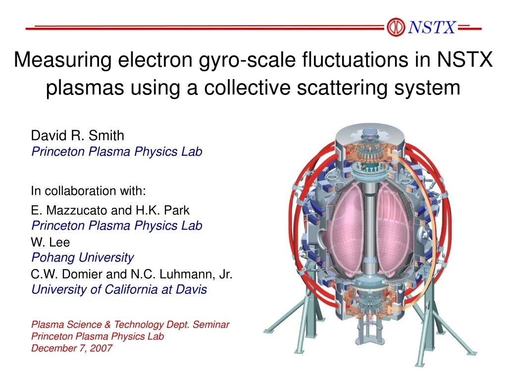
Measuring electron gyro-scale fluctuations in NSTX plasmas using a collective scattering system. David R. Smith Princeton Plasma Physics Lab In collaboration with: E. Mazzucato and H.K. Park Princeton Plasma Physics Lab W. Lee Pohang University

E N D
Measuring electron gyro-scale fluctuations in NSTX plasmas using a collective scattering system David R. SmithPrinceton Plasma Physics Lab In collaboration with: E. Mazzucato and H.K. ParkPrinceton Plasma Physics Lab W. LeePohang University C.W. Domier and N.C. Luhmann, Jr.University of California at Davis Plasma Science & Technology Dept. Seminar Princeton Plasma Physics Lab December 7, 2007
Outline • Motivation • Does electron temperature gradient (ETG) turbulenceproduce meaningful electron thermal transport? • Principles of scattering measurements • The NSTX high-k scattering system • Core fluctuation diagnostic with high sensitivity,spatial localization, k-space selectivity for up tofive distinct wavenumbers, and steerable optics. • Initial measurements and research topics
Transport sets the plasma size neededto attain fusion-relevant conditions The perpendicular particle flux (Γ) andperpendicular energy flux (Q) are key transport quantities 0th moment: 1st moment (SS): 2nd moment: 3rd moment (SS): terms with substantialfluctuation contributions (species subscripts suppressed above)
Fluctuation-induced transporttypically dominates other contributions Fluctuation-induced particle and energy transport The phase between fluctuations is critical. When leads (non-adiabatic response),there is a net motion of particles down the density gradient. The story is the same for energy and .
What drives electron thermal transport? ion gyro-scale turbulence electron gyro-scale turbulence NSTX high-k } well studied exp. & comp. ← long disregardeduntil recently } good confidence in our understanding ← low confidence note that fusiona particles willpreferentiallyheat electrons [Doyle et al., NF 47, S18 (2007)]
Electron thermal transport is typicallythe dominant loss channel in NSTX plasmas Ion thermal transport is at or near neoclassical. It is widely held that ExB flow shear stabilizes ITG/TEM turbulence in NSTX. [see papers by Kaye (07, 06), Levinton (07), Stutman (06), LeBlanc (04), Synakowski (03), Bourdelle (03), Rewolt (96)] Stutman, APS 04 Relation between energy flux Qs and heat flux qs: Common thermal transport model: thermal conductivity
Drift-interchange modes are analogousto the Rayleigh-Taylor instability “Gravity” is ExB drift arising from charge separation due to B/curvature drifts Generic drift-interchange growth rate: [G. Hammett, APS 2007 Review Talk]
Plasma turbulence is anisotropic with k k [Candy, Waltz, and the GYRO team] Remember this for later...
qe R/LTe ETG instability exhibits a critical gradient ETG critical gradient from linear gyrokinetic simulations using GS2[Jenko, PoP 8, 4096 (2001)] ETG critical gradient extendsto nonlinear saturation and electron thermal transport Horton, PoP 112600 (2004)
ETG turbulence can saturate at higher amplitudethan ITG/TEM turbulence due to zonal flow dynamics turbulent Reynolds stress zonal flows drift-wave turbulence (ITG/TEM/ETG) ExB flow shear ETG turbulence generates zonal flows less efficiently thanITG/TEM turbulence because the adiabatic-ions in ETG turbulence have large gyro-orbits compared to ETG-driven zonal flows. Consequently, ETG turbulence saturates at higher amplitude and produces more normalized transport than ITG/TEM turbulence. [see Dorland, PRL (2000) and Nevins, PoP (2006)]
Layout of a scattering system • The intersection of the probe beam and receiving beamdefines the scattering volume • The scattering angle provides k-space selectivity through the Bragg relation: k = 2ki sin(q/2)
Conservation relations describe three-wave couplingamong EM waves and a plasma fluctuation An incident EM wave (ki, ωi) and a plasma fluctuation (k, ω)couple to produce a scattered EM wave (ks, ωs). Energy conservation: ωs = ωi ± ω Momentum conservation: → ks → Bragg relation follows fromhigh frequency incident wave: ωiω ki≈ ks and k = 2ki sin(q/2) k q → ki + gives anti-Stokes interaction- gives Stokes interaction
Fluctuation spectrum can be reconstructedusing multiple detection channels The plasma performs the Fourier transformfrom real space to k-space
Anisotropic turbulence and magnetic field variationcombine to improve spatial localization k’s and θ’s must satisfy: For scattering on the midplane, k’s are purely radial.Some k’s within the overlap volume produce scattered light (ks)that does not intersect the receiver, so the scattering volume is constricted. see Mazzucato, PPCF 48, 1749 (2006)
Density fluctuations encoded intoscattered power spectrum derivedquantities: independentquantities: observation point scatteringvolume → r → ki Scattered power due to a single, coherent fluctuation:
Thomson scattering ω0 = 0 Rayleigh scattering ω0 >> ω Thomson scattering → EM wave scatteringdue to unbound electrons Rayleigh scattering → EM wave scattering due to bound electrons Scattering cross-section, σ, derives from the dipole radiation of an electron, with natural frequency ω0,driven by an EM wave with frequency ω: Classical electron radius:
Two varieties of Thomson scattering:collective and incoherent • Incoherent Thomson scattering • Scattering wavelength →λλD (λ=2π/k) • Random electron motion → incoherent radiation • Dipole powers additive→ Ps ne • Near-IR sources →λ ~ 1 mm • Scattering angle → 90° • Useful for ne and Te measurements • Collective Thomson scattering • Scattering wavelength →λλD • Collective electron motion → coherent radiation • Dipole powers multiplicative→Ps ne2 • Far-IR to mm-wave sources → λ ~ 10 mm to 4 mm • Scattering angles → 1° to 40° • Useful for density fluctuation measurements
NSTX “high-k” scattering systemmeasures fluctuations up to k┴re 0.6 • 280 GHz (l=1 mm) scattering system • Instrumental minimum detectable fluctuation is ñe/ne~10-5 • Five detection channels • k┴ spectrum at five discrete k┴ • ω spectrum from time domain sampling • Tangential scattering • Probe and receiving beams nearly on equatorial midplane • System sensitive to radial fluctuations • Steerable optics • Scattering volume can be positioned throughout the outer half-plasma • First data during FY06 run campaign
Five detection channels can measurefluctuations at five discrete wavenumbers Measurements at R = 142 cm and r/a = 0.79 higher k, smaller λ lower k, larger λ
Steerable optics enable good radial coverage Intermediate ρ = 0.4 k┴ρe up to 0.3 Inboard ρ = 0.05 k┴ρe up to 0.7 Outboard ρ = 0.75 k┴ρe up to 0.2
Scattering system layout • BWO source • outside test cell • ~100 mW at 280 GHz • Overmoded, corrugated waveguide • low-loss transmission • Steerable optics • quasi-optical design • Heterodyne receiver • five channels • reference signal extracted from main beam
Scattering system pictures waveguide and launch optics collection optics heterodynereceiver exit windows collection mirror
Quasi-optical design positions beam waist at scattering location and couples scattered light into receiver • 3 cm beam waist (1/e2 intensity radius)at the scattering location • k-space resolution Δk ≈ 0.7 cm-1
Ray tracing calculations are neededto design configurations prior to experiments Launch mirror (probe beam)Horizontal actuator: 1.117 in.Horizontal angle wrt X-axis: 83.0°Vertical actuator: 1.217 in.Vertical angle wrt midplane: -6.0° Collection mirrorHorizontal actuator: 2.144 in.Horizontal angle wrt X-axis: 232.5°Vertical angle wrt midplane: 5.4°(Vertical angle not adjustable)
Ray tracing calculations are neededto ensure k-space alignment Data is not junk Electron diamag.direction Doppler shiftin ion direction Offset from PB tangency
Ray tracing calculations are neededto determine scattering volume size beamoverlap instrument selectivitydue to k k
Ray tracing calculations are neededto account for refraction with refraction without refraction
Ray tracing calculations are neededto discriminate good data from junk data Good data Mostly good data Junk data
Ray tracing calculations are neededto interpret measurements The time evolution of turbulence parameters,such as kρe and kθ/kr, are needed for comparing data to simulations.
Stray light spectral peak and Doppler-shifted fluctuations are common features High-k measurements at R 135 cm and r/a 0.68 with kρe ~ 0.2-0.3 Fluctuations initially appear in the electron direction, then Doppler-shift to the ion direction due to VT.
Prominent, persistent fluctuationsobserved in core High-k measurements at R 113 cm and r/a 0.25kρe ~ 0.35-0.40 for channel 5 Features appear in the ion direction due to Doppler shift
Prominent, persistent fluctuationsobserved in outer-plasma High-k measurements at R 135 cm and r/a 0.7kρe ~ 0.1-0.3 for channel 2 Ion/electron directions are reversed from previous slide.Fluctuations again experience a Doppler-shift to ion direction.
Using only HHFW heating,unshifted fluctuations observed in core High-k measurements at R 120 cm and r/a 0.3kρe ~ 0.15-0.35 for channel 4 Without toroidal rotation from NBI to produce a Doppler-shiftto the ion direction, fluctuations appear in electron direction.
In some HHFW discharges, peak Te obtainedwhen R/Ln reverses and fluctuations drop High-k measurements at R 120 cm and r/a 0.3 This is a preliminary observation; counter examples exist.
Core fluctuations change characterafter RS collapse High-k measurements at R 120 cm and r/a 0.35kρe ~ 0.15-0.25 for channel 4 and 0.25-0.35 for channel 5 This is a preliminary observation due to stray light concerns.
Unique capabilities may guide future research The NSTX high-k system is the only core fluctuationdiagnostic capable of addressing these questions: k-space isotropy • Are fluctuations isotropic in the kq-kr plane? • Steerable optics provide the capability to address this. Mode coupling • What is the phase coherence among three turbulent fluctuations that satisfy frequency and wave vector matching conditions? • Multiple detection channels provide the capabilityto address this.
Summary • Transport is important • ETG turbulence may be important • Collective scattering is a powerful technique for measuring fluctuations with spatial localization andk-space selectivity • The NSTX high-k system is versatile due to steerable optics and multiple detection channels • Electron gyro-scale fluctuations have been observed exhibiting a variety of dynamics in a variety of NSTX plasmas
Acknowledgements Special thanks to Ben LeBlanc, Ron Bell, Mike Bell, Russ Feder, Stan Kaye, Howard Yuh, Fred Levinton, Joel Hosea, Dave Mikkelson, Greg Hammett, and T.S. Hahm.