Download
1 / 41
420 likes | 571 Views
Designing the Architecture. Architecture in the Life Cycle. When?. Major requirements are identified. Architecture in the Life Cycle. When does one begin designing? Identify the highest priority business goals and turn them into quality scenarios or use cases

E N D
Architecture in the Life Cycle When? Major requirements are identified
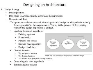
Architecture in the Life Cycle • When does one begin designing? • Identify the highest priority business goals and turn them into quality scenarios or use cases • The ones that have the most impact on the architecture are the architectural drivers (there should be fewer than 10) • Once the architectural drivers are known, the architectural design can begin • The requirements analysis process will then be influenced by questions generated during the architectural design
Evolutionary Delivery Life Cycle Software Concept Deliver Final Version Preliminary Requirements Analysis Design of Architecture and System Core Develop a Version Incorporate Customer Feedback Deliver the Version Elicit Customer Feedback
Designing the Architecture • A method called Attribute Driven Design (ADD) can be used to design an architecture to satisfy both quality and functional requirements. • ADD can be viewed as an extension to other developments methods, such as the Rational Unified Process (RUP).
Attribute-Driven Design • ADD bases the decomposition process on the quality attributes the software has to fulfill. • It is a recursive decomposition process, where, at each stage • tactics and architectural patterns are chosen to satisfy a set of quality scenarios • functionality is allocated to instantiate the module types provided by the pattern.
Inputs of ADD Inputs • Functional requirements • Design constraints • Quality attribute requirements
Functional requirements • The system shall allow users to buy and sell securities. • The system shall allow users to review account activity. • The system shall monitor and record inputs from sensors. • The system shall notify operators of reactor core temperature changes. • The system shall compute and display the orbit and trajectory for all satellites.
Design constraints • Oracle 8.0 shall be used for persistent storage. • System services must be accessible through the World Wide Web. • The system shall be implemented using Visual Basic. • The system shall only interact with other systems via Publish/Subscribe. • The system shall run on both Windows and Unix platforms. • The system shall integrate with legacy applications.
Functional requirements, design constraints, and quality attribute requirements may be implied rather than explicit. • In some cases, it may be difficult to categorize a particular condition as either a functional requirement, design constraint, or quality attribute requirement.
Output of ADD General design of system architectures
Example Application of ADD • Sample problem: A garage door opener within a home information system. • The system is responsible for raising and lowering the door via a switch, remote control, or the home information system. It is also possible to diagnose problems with the opener from within the home information system.
Input to ADD • The device and controls for opening and closing the door are different for the various products in the product line. They may include controls from within a home information system • The processor used in different products will differ.
Input to ADD • If an obstacle (person or object) is detected by the garage door during descent, it must halt within 0.1 second. • The garage door opener should be accessible for diagnosis and administration from within the home information system using a product-specific diagnosis protocol.
ADD Steps • Choose the module to decompose – the module to start with is usually the whole system. • Refine the module according to the following steps: • Choose the architectural drivers from the set of concrete quality scenarios and functional requirements. • Choose an architectural pattern that satisfies the architectural drivers based on the tactics that can be used to achieve the drivers.
ADD Steps • Refine the module according to the following steps (cont’d): • Instantiate modules and allocate functionality from the use cases and represent using multiple views. • Define interfaces of the child modules. The decomposition provides modules and constraints on the types of module interactions. Document this information in the interface document for each module.
ADD Steps • Refine the module according to the following steps (cont’d): • Verify and refine use cases and quality scenarios and make them constraints for child modules. • Repeat the steps above for every module that needs further decomposition.
1. Choose the Modules to Decompose • In our example, we start with the whole system, the garage door opener system. • One constraint at this level is that the opener must interoperate with the home information system.
2a. Choose the Architectural Drivers • The four scenarios previously given indicate requirements for: • real-time performance • modifiability to support product lines • online diagnosis • In general, a detailed investigation may be required to determine whether given requirements are really drivers.
2a. Choose the Architectural Drivers • We do not treat all requirements as equal. • The less important requirements are satisfied within the constraints of the most important.
2b. Choose an Architectural Pattern • The use of an interpreter is an excellent technique for achieving modifiability at runtime, but it has a negative influence on performance. • The decision to use an interpreter depends on the relative importance of modifiability versus performance. • A possible decision is to use an interpreter for only a portion of the pattern.
2b. Choose an Architectural Pattern • The modifiability tactics are “localize changes,” “prevent the ripple effect,” and “defer binding time.” • In this case, where we are concerned primarily with changes that will occur during system design, the primary tactic is “localize changes.” • We choose semantic coherence and information hiding as our tactics and combine them to define virtual machines for the affected areas.
2b. Choose an Architectural Pattern • The performance tactics are “resource demand” and “resource arbitration.” • We choose one example of each: “increase computational efficiency” and “choose scheduling policy.” • The final set of tactics is therefore: • Semantic coherence and information hiding – Separate responsibilities dealing with the user interface, communication, and sensors into their own modules (virtual machines).
2b. Choose an Architectural Pattern • The final set of tactics (cont’d): • Increase computational efficiency – The performance-critical computations should be made as efficient as possible. • Schedule wisely – The performance-critical computations should be scheduled to ensure the achievement of the timing deadline.
Architectural Pattern that Utilizes Tactics to Achieve Garage Door Drivers User Interface Non-Performance- Critical Computation Performance-Critical Computation Virtual Machine Schedule that Guarantees Deadlines
2c. Instantiate Modules and Allocate Functionality Using Multiple Views • We allocate the responsibility for managing obstacle detection and halting the garage door to the performance-critical section since the functionality has a deadline. • The management of the normal raising and lowering of the door has no timing deadline so we can treat it as non-performance-critical
2c. Instantiate Modules and Allocate Functionality Using Multiple Views • The diagnosis capabilities are also non-performance-critical. • We also identify several responsibilities of the virtual machine: communication and sensor reading and actuator control.
First-Level Decomposition of Garage Door Opener User Interface Diagnose Raising/Lowering Door Obstacle Detection Communication Virtual Machine Sensor/Actuator Virtual Machine Scheduler that Guarantees Deadlines
2c. Instantiate Modules and Allocate Functionality Using Multiple Views • Applying use cases that pertain to the parent module helps the architect gain a better understanding of the distribution of functionality. • Ultimately, every use case of the parent module must be representable by a sequence of responsibilities within the child modules.
2c. Instantiate Modules and Allocate Functionality Using Multiple Views • The three common views • Module decomposition view – Containers for holding responsibilities and the major flow relationships among the modules • Concurrency view – Dynamic aspects of a system such as parallel activities and synchronization can be modeled • Deployment view – The allocation of threads
2d. Define Interfaces of the Child Modules • An interface of a module shows the services and properties provided and required. • Analyzing and documenting the decomposition in terms of structure (module decomposition view), dynamism (concurrency view) and runtime (deployment view) uncovers the interaction assumptions for the child modules.
2e. Verify and Refine Use Cases and Quality Scenarios • Each child module has responsibilities that need to be translated into use cases for the module. Use case can also be defined by splitting and refining the parent use cases. • For the garage door opener system, the responsibilities are decomposed into the following functional groups • User interface – recognize user requests and translate them into the form expected by the raising/lowering door module
2e. Verify and Refine Use Cases and Quality Scenario • Raising/lowering door module – Control actuators to raise or lower the door. Stop the door when it reaches either fully open or fully closed. • Obstacle detection – recognize when an obstacle is detected and either stop the descent of the door or reverse it.
2e. Verify and Refine Use Cases and Quality Scenarios • Communication virtual machine – Manage all communication with the home information system. • Sensor/actuator virtual machine – Manage all interactions with the sensors and actuators. • Scheduler – Guarantee that the obstacle detector will meet its deadlines. • Diagnosis – Manage the interactions with the home information system devoted to diagnosis.
2e. Verify and Refine Use Cases and Quality Scenarios • The constraints of the parent module can be satisfied in one of the following ways: • The decomposition satisfies the constraint • The constraint is satisfied by a single child module • The constraint is satisfied by multiple child modules
2e. Verify and Refine Use Cases and Quality Scenarios • In the garage door opener system, one constraint is that the communication with the home information system is maintained. • The communication virtual machine will recognize if this communication is unavailable, so the constraint is satisfied by a single child.
2e. Verify and Refine Use Cases and Quality Scenarios • Quality scenarios also need to be refined and assigned to child modules: • A quality scenario may be completely satisfied by the decomposition without any additional impact • A quality scenario may be satisfied by the current decomposition with constraints on child modules. • The decomposition may be neutral with respect to a quality scenario, e.g., a usability scenario, in which case it should be assigned to one of the child modules. • A quality scenario may not be satisfiable with the current decomposition. Either the decomposition should be reconsidered or rationale justifying its omission must be provided.
Refined Quality Scenarios for the Garage Door Opener Example • The devices and controls for opening and closing the door are different for different products in the product line. They may include controls from within a home information system. This scenario is delegated to the user interface module. • The processor used in different products will differ. This scenario is delegated to all of the modules. Each module becomes responsible for not using processor-specific features not supported by standard compilers.
Refined Quality Scenarios for the Garage Door Opener Example • If an obstacle is detected by the garage door during descent, the door must halt (or re-open) within 0.1 second. This scenario is delegated to the scheduler and the obstacle detection module. • The garage door opener should be accessible for diagnosis and administration from within the home information system using a product-specific diagnosis protocol. This scenario is split between the diagnosis and communication modules.
Status at the End of the Iteration • We now have a decomposition of a module into its children. • Each child has a collection of responsibilities: • A set of use cases • An interface • Quality scenarios • A collection of constraints • This is sufficient to start the next iteration of the decomposition
Forming the Team Structure • Once the first few levels of the architecture’s module decomposition structure are fairly stable, those modules can be allocated to development teams. • Within teams there needs to be high-bandwidth communications. • Between teams, low-bandwidth communications are sufficient (and in fact crucial).