Download
1 / 49
530 likes | 797 Views
DVM PLUS III INSTALLATION (Preliminary). DVM PLUS III line up. Space requirements. 1) Single installation. 2) Group installation. Installing outdoor unit. Anchor bolt position. Remove stopper. ■ Remove stopper √ 10 Ton : 4 pieces of stopper in legs of compressor

E N D
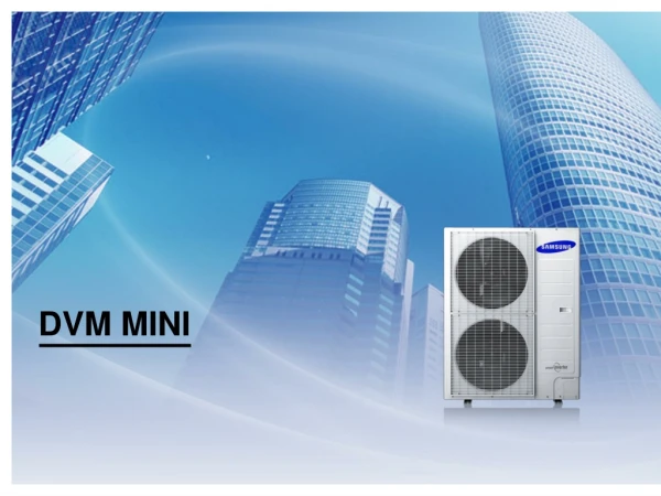
DVM PLUS III INSTALLATION (Preliminary)
Space requirements 1) Single installation 2) Group installation
Remove stopper ■ Remove stopper √ 10 Ton : 4 pieces of stopper in legs of compressor The stopper is just using only for transportation, not operation
Piping layouts (HP) ■ Y joint only ■ Y joint with Header joint
Piping length (HP) Y joint Main pipe 1st Refnet Joint
Main pipe 1 size increasing Examples Example) 34 HP • With 1 bigger size, it can increase cooling capacity by 16.8 %.
Selection the refrigerant pipe 1. 명기된 사양은 개발진행에 따라 변경 될 수 있습니다. 2. 배관은 미주 지역에서 구입 가능한 배관으로 선정되어 있습니다. 현지에서 구매가 불가능한 배관을 제외(1, 1 ¼, 1 ½ )하였기에, 배관 선정 사양이 기존의 DVM PLUS 2 대비 해서, 변경될 소지가 있으니 참고 하시길 바랍니다. (위에 말씀 드린 것처럼 첨부된 문서의 설치 사양은 변경될 소지가 있습니다.)
■ Definitions A1 Outdoor unit Branched pipes from outdoor joints to outdoor Branched pipes between outdoor joints A2 Main Pipes A3 Branched pipes between branch joints B C Pipes to indoor units Outdoor joints D Branch joints (Indoor joints) E, F
■ Step 1 – Select pipes to outdoor units from ‘outdoor joints’ A1 ■ Step 2 – Select pipes between outdoor joints A2
■ Step 3 – Upsizing “Main” pipes, When? Outdoor unit A3 The farthest indoor unit If the piping length between outdoor to the farthest indoor unit is over 90m (295ft), use right table. A3
■ Step 4 – Select ‘Outdoor joints’ D ■ Step 5 – Select the first ‘Branch joints’ E
■ Step 5 – Example RVXVHT125FE RVXVHT100FE RVXVHT125FE Liquid : 1/2 Gas : 1 1/8 Liquid : 1/2 Gas : 1 1/8 (A1) (A1) Liquid : 5/8 Gas : 1 1/8 Liquid : 3/8 Gas : 7/8 (A2) (A1) A2 capacity = A1 capacity + A1 capacity Example) A1 : 7.5 HP → Liquid : 3/8”, Gas : 3/4” A1 : 7.5 HP → Liquid : 3/8”, Gas : 3/4” A2 : 15.0 HP → Liquid : 1/2”, Gas : 1 1/8”
■ Step 6 – Select branched pipes between ‘branch joints’ B ■ Step 7 – Select ‘Branch joints’ F
Additional refrigerant √ Additional refrigerant has to be charged according to the length and size of liquid pipe.
Outdoor joint (HP, HR) Ex) MXJ-T3819*, MXJ-T4422 - Liquid connection - Gas connection
Outdoor joint (HR Only) Ex) MXJ-T3100* - High pressure gas connection
Y- joint (HP, HR) Ex) MXJ-YA1509
Y- joint (HR Only) Ex) MXJ-YA1500 ~ MXJ-YA3800
Header- joint (HP only) Ex) MXJ-HA2512
Outdoor units piping ■ Refrigerant piping should be the same level or lower than connecting position. Accumulating of oil
Outdoor units piping ■ Refrigerant piping should be connected with side direction. Unbalancing of Ref. & oil distribution Refrigerant can excessively leans to one direction.
Outdoor units piping ■ Refrigerant piping should be connected with side direction. Refrigerant can excessively leans to one direction.
Outdoor units piping ■ Refrigerant piping should be installed in a horizontal direction. Be horizontal Min. 4 inch
Vertical trap Outdoor units piping ■ Vertical trap 8 ~ 12 inch 40 inch 80 inch 80 inch
Outdoor units piping ■ Connecting the outdoor unit pipe Front connection Front connection Oil valve size : 1/4 inch Bottom connection Bottom connection
Y joint installation Refnet Y Joint Installation Y Joint Horizontally installed Vertically installed Vaporized refrigerant leans to upper direction in Y joint. For uniform refrigerant distribution
Header joint installation Refnet Head Joint Installation Header Joint Liquid head Joint Vaporized refrigerant leans to one of direction in branch joint. Header Joint Gas head Joint Do not install vertically.
Header joint installation Connect according to larger capacity of indoor unit in order
Piping work Taping Nitrogen replacement before brazing Without nitrogen gas blowing With nitrogen gas blowing
Insulation work ※ Application condition : indoor temperature : 80℉, 80% RH
Wiring work 3 Phase 3 wires Caution Be sure to install the switch and the fuse to the power line of each equipment. (Field wiring work)
Wiring work Caution of wiring work 208 ~ 230V 208 ~ 230V 208 ~ 230V Hold wiring with using cable tie Note Use ring terminal for wiring terminal block
Vacuum drying Oil piping should be performed a vacuum
Setting option switch Outdoor’s control part PCB Transformer Filter PCB Magnet CT Sensor BLDC Fan Driver Power TB Outdoor-indoor unit communication Outdoor – outdoor unit communication
Setting option switch Sensor 220 V output