Download
1 / 46
460 likes | 465 Views
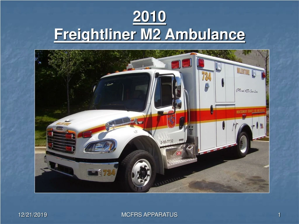
2010 Freightliner M2 Ambulance. Specification Chart. Engine Cummins 6.7 liter 240 HP Brakes Antilock air S-Cam drum Front axle 8,000 lb. GAWR Rear axle 12,000 lb. GAWR

E N D
2010Freightliner M2 Ambulance MCFRS APPARATUS
Specification Chart • Engine Cummins 6.7 liter 240 HP • Brakes Antilock air S-Cam drum • Front axle 8,000 lb. GAWR • Rear axle 12,000 lb. GAWR • Actual unit weight 15,500 lb. empty • Unit height 10’ 6” (126”) • Unit length 23’ 6” (282”) • Alternator 270 amp • Coolant Shop approved Ethylene Glycol • Engine oil 15-40 weight ultra flow CJ-4 • Transmission EVS 3000 Trans-Synd only • Air compressor Bendix 13.2 cfm • Power steering fluid Dexron lll transmission fluid MCFRS APPARATUS
General Information • Before starting the unit allow the gauges to complete a sweep. This will take approximately seven seconds. • There is no battery kill switch on these units. All electrical devices and headlights must be shut off or dead batteries will result. • The parking brake will not release until the brake light in the dash cluster goes out. Until the brake releases, the transmission will not engage. • The master, sequencer, and primary switch must all be on for the air horns to function. • Fast idle automatically engages when the emergency master is on and the parking brake is set. • Never mix fluids for any reason. Do not cross contaminate fluids by using the same container to add multiple fluid types. MCFRS APPARATUS
Exhaust brake CAUTION • A exhaust brake works by retarding the engine by creating a high exhaust pressure. These units are equipped with a exhaust brake. The exhaust brake will not be used in low traction or slippery conditions. MCFRS APPARATUS
Exhaust brake • A exhaust brake works by retarding the engine by creating a high exhaust pressure. • As the engine speed slows so does the drive train which in turn slows the unit. • When low traction or slippery conditions exist turn the exhaust brake off. MCFRS APPARATUS
Engine Compartment Right (Officer’s) Side 3 1 4 2 MCFRS APPARATUS
Engine Compartment Left (Driver’s) Side 4 3 5 2 6 1 MCFRS APPARATUS
Right Side Components Air dryer The air dryer is located mid frame. The air dryer should purge at approximately 120 psi. MCFRS APPARATUS
Arrow Transmission Fluid Check • The transmission fluid level may be checked in the cab thru the key pad selector. • The engine must be running at idle and the unit must be on level ground. • The engine must idle at least five minutes from a cold start. • The transmission must heat to at least 140 degrees F. • Push both the up and down arrow buttons at the same time on the key pad. MCFRS APPARATUS
Transmission Fluid Check • After simultaneously pushing both buttons, the symbol “OL” (Oil Level) will display in the screen. • “OL” will be followed by one of the following: OK. -1 thru 7, or + 1 thru 7. The “ – “ indicates under filled, “+” indicates overfilled, and the numeral represents the number of quarts. • Any other message indicates another problem. You should consult the shop. • Always confirm + or – readings by manually checking the dipstick before adding or requesting to drain fluid. • Remember, only Trans-Synd transmission fluid can be used. MCFRS APPARATUS
Reverse Camera Video screen is located in the right side of the rear view mirror MCFRS APPARATUS
Air Brake System • These units are the only EMS units in the fleet equipped with air brakes. • They also have a 4S-4M anti-lock brake system. • The brakes are S-Cam drum type. • The air compressor is a Bendix 18.5 cfm. • Each unit has four air reservoirs and three air tanks. • On one end of each air reservoir there is an manual valve. • The air dryer is located mid frame on the left frame rail . MCFRS APPARATUS
Air Brake System • Air is drawn into the air compressor through the air cleaner. The air is compressed and sent to the air dryer. The air dryer removes 95 to 98% of the moisture and oil vapor from the compressed air. • The dried air leaves the dryer and is sent to the supply or, wet tank where it decompresses and is routed to the primary, secondary, or accessory reservoirs. • When the air reservoirs come to full pressure the air governor disengages the air compressor and activates the air dryer to purge its contents to atmosphere. • The air gauge on the dash should read approximately 120 to 135 psi. when the air dryer purges MCFRS APPARATUS
Air Brake System Air discharge to air dryer Air intake Air from dryer to wet tank Bendix AD-IP heated air dryer Bendix 13.2 cfm air compressor MCFRS APPARATUS
Automatic moisture ejector Air Brake System There are four air reservoirs on the unit, but only three air tanks. The wet and primary air system share the same compartmented tank. There is a secondary tank followed by an accessory tank. All tanks are equipped with a automatic moisture ejectors. MCFRS APPARATUS
Spring brake side of chamber Air Brake System Rear brake chamber When you apply pressure to the brake pedal, air leaves the tanks and enters the brake chambers engaging the service brakes. When you apply the parking brake, air is evacuated from the chamber allowing the spring (parking) brake to apply. Always report corrosion or damage to any brake chamber. MCFRS APPARATUS
ABS line Air line Brake chamber Clevis pins Clevis Slack adjuster Air Brake System When air enters the service chamber it pushes on a diaphragm which in turn pushes the push rod and slack adjuster forward. The slack adjuster turns the S-Camshaft and forces the shoes against the brake drum. MCFRS APPARATUS
¼ inch line Brake block Brake drum Bevel Air Brake System There are two brake blocks per shoe. There are two ways to check and see if you have proper braking material. Look at the bevel, if bevel is not visible you are at ¼ inch. Some manufactures have the marking line but not all. When you get down to the line you are at ¼ inch. Any drum brake with less than ¼ inch of pad is Out Of Service MCFRS APPARATUS
Remote Door Lock Button To secure the unit, push the switch and all doors and compartments will lock. Then close the door. The rear lock button is located next to the air dump override. MCFRS APPARATUS
Remote Door Unlock Button To un-secure the unit, open the ‘stealth’ cover and push the button. The unit is now unlocked. MCFRS APPARATUS
Zico Oxygen Lift Unlock This is a three position switch. Push down to lower the unit. The center position is neutral. Push the button up to raise the unit. Lock Before lowering the oxygen M-cylinder, unlock the bracket. Slide the arm up to unlock, down to lock. Stop lowering the unit as soon as it touches the ground. Do not force the unit beyond this point. MCFRS APPARATUS
Above drivers head Between driver and passenger Cab Features Electrical switches This is the way the emergency switches will be left when in routine status. The Master and Sequencer switch will be off.When the Master switch is on and the parking brake is set, the fast idle is automatically activated.Fast idle can also be achieved by using the cruise control switches. MCFRS APPARATUS
Cab Features Headlight and speed control Cruise control and fast idle For fast idle using cruise control switches, just toggle the switch up and let go. This will give you 1000 rpm. MCFRS APPARATUS
Cab Features Battery switch • The switch marked batteries is a momentary switch. • This switch allows the unit to have electrical power for five minutes. • After five minutes the power will go off. MCFRS APPARATUS
Adjustment pedal Cab Features Steering wheel and column adjustment Step on adjustment pedal for telescoping and tilt functions. Releasing the pedal will lock steering wheel in place. MCFRS APPARATUS
Cab Features Use of this switch will lock/unlock the entire unit. If the doors are inadvertently locked, they can be unlocked with the stealth switch on the rear of unit MCFRS APPARATUS
Cab Features Traction control This switch is located between the driver and officer on the dash. In the event of a wheel spin, stop the unit and activate the traction control switch. The switch will illuminate and lock the left and right rear wheels together. You will now have both rear wheels with equal power. **NOTE** When the rear wheels are locked together and spin, the rear of the unit will follow the slope of the ground. MCFRS APPARATUS
Cab Features Mirrors Both side mirrors are heated. Only the top mirror is controlled automatically, the bottom mirror must be adjusted manually MCFRS APPARATUS
Mirror adjustment Mirror select Cab Features Mirror heat MCFRS APPARATUS
Adjustment screw Cab Features Adjustable arm rests There are two arm rests per seat. To adjust the height of the arm rest turn the adjusting screw clockwise for down, counterclockwise for up. MCFRS APPARATUS
Jumper Studs The jumper studs are located under the drivers compartment. When jumping a dead battery the order is as follows: LiveRed to Dead Red (+) Dead Black (-) to a grounding point on the starting vehicle. The jumper studs are now located on the drivers side frame rail behind the front tire. MCFRS APPARATUS
DPF REGENERATION • In 2010 all diesel exhaust systems must be fitted with a DPF with a regeneration system. • DPF is Diesel Particulate Filter which captures soot and ash from the engine exhaust. • Regeneration is the process of burning off the soot and ash. • There are two types of regeneration: 1. Passive which requires no driver involvement. 2. Active which requires driver involvement. • Warning lights in the dash cluster will advise the driver of what action is needed. Refer to the chart on the drivers sun visor. MCFRS APPARATUS
DPF REGENERATION Active Parked Regeneration • When the DPF lamp is blinking and a solid check engine lamp is illuminated a parked regeneration is required. • During a regeneration exhaust temperature can reach 1300 degrees, select a appropriate location. • Park unit, place the transmission in neutral, chock the wheel, toggle the regeneration switch. Engine rpm should increase to approximately 1100rpm. • Keep exhaust 5 feet away from all objects and pedestrians. • The driver must remain with the vehicle during regeneration. MCFRS APPARATUS
DPF REGENERATION • During the regeneration process the high exhaust temperature lamp will illuminate. • When the ECM determines the DPF has been regenerated engine rpm will decrease to normal rpm signaling the regeneration is over. • Remember exhaust components are still very hot. • If the regeneration process needs to be interrupted, or stopped, depress the brake pedal. MCFRS APPARATUS
DPF REGENERATION The regeneration switch is located in the center of the dash next to the door lock switch. MCFRS APPARATUS
Dash warning lights for DPF MCFRS APPARATUS
Department of Transportation (D.O.T) Air Brake Test This brake test must be performed in the following order. Before you begin the test be sure thatthe wheels are chocked! Make sure the ignition is on so gauges will read and warning devices will sound. MCFRS APPARATUS
D.O.T Air Brake Test Ensure the Parking Brake is applied (pull), to take air off the system allowing the spring brake to hold the rear wheels. Freightliner M2 ambulances have two air gauges. The top gauge is for the primary air system. ( rear brakes) The lower gauge is for the secondary air system. ( front brakes) MCFRS APPARATUS
D.O.T Air Brake Test Push the parking brake release in. This allows air to enter the brake chambers, pushing off the spring brake. You may see air loss on the gauges or indicator needles wiggle as they settle to a balanced pressure. When the needles stop moving, start timing. An air leak cannot exceed 3 psi within a one minute time frame. MCFRS APPARATUS
D.O.T Air brake test After one minute, place your foot on the brake pedal and hold steady pressure. You should notice a pressure loss, after the needles stop moving, start timing for one minute. An air leak cannot exceed 3 psi within a one minute time frame MCFRS APPARATUS
Warning lights D.O.T Air Brake Test After one minute of steady pressure, you will begin the next test. Start rapidly pressing and releasing the brake pedal (fan the pedal) bringing your air gauges down. Between 60 and 90 psi you should get a light and a buzzer Between 20 and 40 psi the parking brake release will activate (pop) allowing the mechanical spring brake to apply. MCFRS APPARATUS
D.O.T Air Brake Test When the parking brake applies, this portion of the test is complete. You will now start the engine and let the air gauge build to 50 psi. When it reaches 50 psi, start timing while watching the gauge. At 1200 rpm, air pressure must reach 90 psi in 90 seconds MCFRS APPARATUS
D.O.T Air Brake Test Continue running the engine until you hear the air dryer purge. This will occur at approximately 120 to 135 psi . This indicates that the compressor is now unloaded and not sending air to the tanks. This concludes the D.O.T. brake test. However, we will now verify the compressor cut in pressure. MCFRS APPARATUS
Compressor Cut In Test With the motor still running at idle, release the parking brake and start a slow fanning of the brakes. While watching the air gauges; at approximately 100- to 110 psi the pressure should begin to climb. The compressor is now running and loading the tanks, allowing pressure to build in the reservoirs until you hear the air dryer purge. Note: If the compressor cuts in below 90 psi, notify the shop This concludes the air brake test, set your parking brake and pick up the wheel chock. MCFRS APPARATUS
On Spot chains • Due to the axle configuration of these units the spot chains mount differently • The spot chains face the rear and swing forward. • This creates a problem when backing up to a curb. MCFRS APPARATUS
On Spot chains • When backing into a curb only back until the rear step overhangs the curb. • Do not back until the tires hit the curb. MCFRS APPARATUS