Download
1 / 37
550 likes | 1.12k Views
CLUTCH SERVICE. Teknik Kendaraan Ringan Semester 3 th Class XI Kompetensi Kejuruan SK-KD 7 TH. DIAGRAM ALUR PENCAPAIAN KOMPETENSI. Drive Train. This mechanism consists of: Clutch (clutch) Transmission Propeller shaft Differential Axle & Drive shaft .

E N D
CLUTCH SERVICE TeknikKendaraanRingan Semester 3 thClass XI KompetensiKejuruan SK-KD 7TH
Drive Train • This mechanism consists of: • Clutch (clutch) • Transmission • Propeller shaft • Differential • Axle & Drive shaft • Mechanism changes energy generated by a machine called the "Power Train"
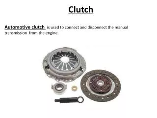
Clutch Terms: Can connected from engine to the transmission with smooth Can move the engine to power transmission without slip Can terminate the relationship with the quick and perfect Position: Between the engine and transmission Function: To connect and disconnect cycles engine to the transmission
Cluct systems are used to disengage the engine from road • When the clucth pedal is depressed, the clucth is disengaged from the engine • When the clutch is engaged the engine, the engine power will transfer through the clucth to the road
SYSTEM COMPONENTS • Flywheel: Transfer engine power the clucth • Input shaft: transfers power from clucth to the tranmission • Clucth Disc : spilne to input sahft, transfer power from engine the input shaft • Pressure plat assembly : Spring pressure tighttly holds the clucth to the flywheel
Release Bearing : Connected through linkage to the clucth pedal. Provides a way for the pressure plate to release pressure on the clucth • Clucth Fork : Slide the release bearing into and away from the pressure plat assembly • ClucthLingkage. Allows the driver to operate the clucth fork • Clucth Housing : Encloses the clucth assembly
Clutches operation Pilot bushing or bearing in center of flywheel or crankshaft, supports the end of input shaft (friction disk) splined to transmission Input shaft (throw-out bearing T/O bearing) allows to push on rotating clutch fingers Bolted to Crank Bolted to flywheel - Applies the spring force to clamp the friction disk to the flywheel (clutch fork) pushes T/O bearing to release rotating clutch
With you foot off of the pedal, the pressute plat hold the clucth against the flywheel, alloing power to travel through the clucth to the input shaft of the transmission
With the clucthdisesaged, the pressure releases it’s clamp on the clucth disc, which interrupts the power flow from engine
Clutches • Flywheel, Pressure plate, spring, end clucth cover are revolving. Clucth disc and clucth shaft are stopped to pressure plat Disengage • Pressure plate engage- seizes clucth disc and entire unit revolves
Fly Wheels • Mounted on the rear of crankshaft • Control speed fluctuations of the crankshaft • Allows a method of starting the engine • Friction surface for the clucth • Cast iron or cold rolled steel
Transmission input shaft • Extends from the rear of engine crankshaft to the insade of the transmission case • Splined area where the clucth hub rides • Pilot area support front of input shaft in end of crankshaft • Transmission front bearing supports the end of the input shaft • Also called the clucth shaft
Clucth Disc • Also called the friction disc • Located between the flywheel and pressure plat • Transmits power from engine to the input shaft • Made up of an outer disc assembly and central hub • Contains many grooves cut across surface for heart dissipation, removal of dust and dirt, and to break and vacum
Splines to input shaft Of transmission Clutch Disk or Friction Disk Construction of the Clutch
Outer disc assembly • Thin steel sandwiched between friction material or friction facing • Friction material is bonded or riveted • Friction material is devaiced into segments for even distribution • Spring steel between the facings help absorp the shock of engagement
Clucth Disc Facings • Clucth Disc Facings • Like brake lining, asbeston was trasitionally used because of excellent coefficient of friction, heat dissipation. And low cost • Fedeal low as banned the manufacture of asbeston containing clucth facings after Agustus of 1992 • Asbeston is replaced with fiberglass and aramid nonmetallic compounds of metallic friction facings, using various mixtures of powdered iron copper, graphite, and ceramic
0,015 or less above rivets is considered worn out • When sectional lines come close to disappering is worn
Friction disks • Often made of asbestos • Must be put in only one way • Usually marked • Clutch won’t release if wrong
Friction disks • Cushion springs • Waved metal between clutch half's • Dampen clutch engagement
Friction disks • Torsional springs • Can be spring or rubber • Dampen power impulses from crankshaft
Torsional Springs Has pins to limit amount of twist. Springs try to keep it centered between pins. Springs sometimes get weak and start rattling or fall out
Disc clutch • Function: • Friction facing the field to play power forward from the engine to the transmission • Cushion plate to soften when the clutch related • Torsion damper for muted surprise when clutch related
Friction disks • Torsional springs • Can be spring or rubber • Dampen power impulses from crankshaft
Hub flange • Splined hub engage the splines on the transmission input shaft • Made from cast iron • Hub flange and outer disc are riveted together with”stop pins”
Types of Clutches (pressure plates) • Coil spring • 9 spring • 12 spring • 3 fingers for T/O bearing to push on
Clutch cover tipe coil spring • Clutch cover type coil spring Advantages: • The emphasis on strong plate clutch Disadvantages: • Energy to pressure plate clutch weight • Construction complicated, so expensive price
Clutch cover type diagpragm • Diaphragm clutch cover model Advantages: • Light energy emphasis • Emphasis clutch plate more evenly • Pedal power is not reduced by the style centrifugal • Disadvantages • The emphasis of the plate clutch smaller
Mechanism of mechanical clutch Freeplay is the distance between the pedal and diaprahgma cushion liberator Free play
Mechanism of hydraulic clutch This type of movement on the clutch pedal to be changed by pressure hydraulic master cylinder which is then forwarded to the release fork through the release cylinder
Master Cylinder Function: To generate pressure hydrolic
Clutch Release Cylinder Function: To forward the power of the master cylinder push release fork
Some are adjustable for free-play and some not
Automatic clutch (torque converter) Note: Only used on vehicles equipped with automatic transmission