Download
1 / 19
220 likes | 444 Views
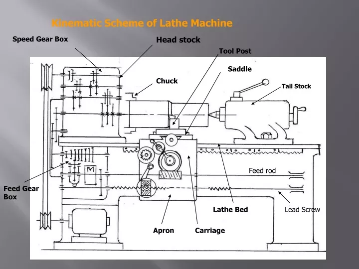
Kinematic Scheme of Lathe Machine. Speed Gear Box. Head stock. Tool Post. Saddle. Chuck. Tail Stock. Feed rod. Feed Gear Box. Lathe Bed. Lead Screw. Apron. Carriage. Lathe Machine – Pulley driven (Light Duty). Lathe – All geared.

E N D
Kinematic Scheme of Lathe Machine Speed Gear Box Head stock Tool Post Saddle Chuck Tail Stock Feed rod Feed Gear Box Lathe Bed Lead Screw Apron Carriage
A capstan lathe or a turret lathe is a production lathe used to manufacture any number of identical pieces in the minimum time. • These lathes are development of engine lathes. • The capstan lathe was first developed in the United States of America by Pratt and Whitney sometimes in 1860. • Special characteristics of a capstan or turret lathe enable it to perform a series of operations such as drilling, turning, boring, thread cutting, chamfering, cutting- off and many other operations in a regular sequence to produce a large number of identical pieces in a minimum time.
A – Turret Locking Handle, B – Turret, C - Capstan Slide, E - Capstan Slide Block, D - Capstan Rest, F - Sliding Bridge
Principal parts of capstan and turret lathes • The turret has essentially the same parts as the engine lathe except the turret and the complex mechanism Different parts of Capstan lathe are • Head stock • Cross-slide tool post • Hexagonal turret • Saddle for auxiliary slide • Auxiliary slide • Feed rod • Saddle for cross-slide.
Different parts of turret lathe are: • Head stock • Cross-slide tool post • Hexagonal turret • Turret saddle • Feed rod • Saddle for cross-slide.
Bed: • The bed is a long box like casting provided with accurate guide ways upon which are mounted the carriage and turret saddle. • The bed is designed to ensure strength, rigidity and permanency of alignment under heavy duty service Headstock: • The headstock is a large casting located at the left hand end of the bed. The headstock of capstan and turret lathe may be of the following types. 1.Step cone pulley driven headstock 2.Direct electric motor driven headstock 3.All geared headstock
CROSS-SLIDE&SADDLE: • The larger capstan lathes and heavy duty turret lathes equipped with usually two designs of carriage • 1.Conventional type carriage 2.Side hung type carriage • Conventional type carriage bridges the gap between the front and rear bed way sand is equipped with four station type tool post at the front, and one rear tool post at the back of the cross-slide. • The side hung type carriage is generally fitted with heavy duty turret lathes where the saddle rides on the top and bottom guide ways on the front of the lathe bed